

Baudot Teletype Interface – Electronics
This was my first published article, and fell out of my work on the homebrew 8008 system that is now in the Computer History Museum (that link includes four detailed photos). It’s basically a one-way simple UAR/T, though those devices were pricey back then… and this design induces the host micro to wait while a character is sent (an interrupt would be better, of course, but my primitive software wasn’t doing anything else at the time). Of course, now one would eschew expensive external hardware and just use a port bit, but this was 1974 and static RAM locations were a scarce resource.
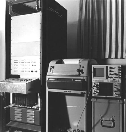
This article had the effect of kindling the crazy notion of writing about my projects, and that became a career. I was 21 at the time, living in an apartment in Kentucky, starting a microprocessor business to escape employment. A photo of my living room, including the machine and the amazing Model 28 teletype, is below the article.

Interfacing a Teletypewriter with an IC Microprocessor
Designer’s Casebook feature
by Steven K. Roberts
Electronics Magazine
July 25, 1974
(written May 13, 1974)
The lengthy software service routine generally required to interface a teletypewriter and an IC microprocessor, such as the Intel 8008, can be eliminated by the circuit shown here. A shift register and some control logic are all that it takes, bringing total component cost to only about $6.50.
In the 8008 system, synchronization with the central processing unit is accomplished through this microprocessor’s READY line, making modification of the teletypewriter itself unnecessary. The hardware configuration given in the figure is designed for a 10 character-per-second Model 28 Teletype, which uses the five-level Baudot code. If the intended application will not easily accommodate data storage in the Baudot code, conversion may be accomplished with a read-only memory, such as National’s MM5221TM. (A Model 33 Teletype presents no decoding problem.)
During the time that the input parallel data is valid, the circuit receives the START pulse, which sets the BUSY flip-flop and takes the READY line low. The BUSY flip-flop also removes the reset from the cycle counter and enables the LOAD flip-flop, which is set on the next clock pulse. This action loads the data at the input to the shift register and increments the cycle counter once.
On the succeeding clock pulse, the ENABLE flip-flop is set, and the data in the register begins to shift to the right. For each shift pulse, the cycle counter is incremented by one until it reaches a binary count of 8. Then, the BUSY and ENABLE flip-flops are both reset, and the READY signal is restored to the microprocessor so that the central-processing unit can resume operation.
In the data character presented to the shift register, bit H, which is constantly held low, corresponds to the teletypewriter START pulse. Similarly, the register’s A and B bits are tied high, corresponding to the teletypewriter STOP pulse. Since the STOP signal must be applied to the teletypewriter for approximately 1.5 times longer than the other pulses, the BUSY flip-flop is reset on the falling edge of the clock, during the time that bit A is present at the register’s QH output. The serial output of the register switches the 60-milliampere teletypewriter current loop through the transistor.
The clock signal for the circuit is derived from the IC timer that is free-running at approximately 75 hertz. For teletypewriters that operate at 6 characters per second, the clock frequency should be about 45.5 Hz.

In 1974-75, I used that Model 28 heavily… including generation of wrappers for my Cybertronic Systems parts catalogs, working from a database I maintained on fanfold paper tape with a Friden reader and punch interfaced to the same 8008 system.

Here is the machine in my apartment living room, early 1975:
You must be logged in to post a comment.