“The time required to complete a task is inversely proportional to the number of words required to express it.”
— The Roberts Law of Creeping To-Do List Complexity
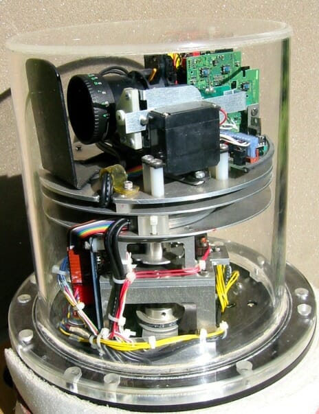
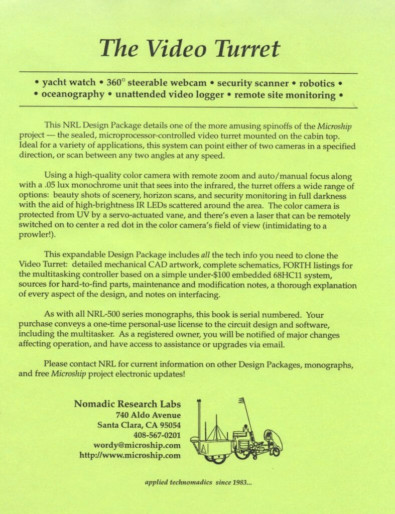
ABSTRACT: This is the complete design for a microprocessor-controlled, environmentally sealed 8″ video turret with two cameras, remote or autofocus, zoom control, sun damage protection, 450-degree azimuth rotation, 9-speed scan and point capability, multidrop network connection, and extensive expandability. Included here are detailed photos, complete schematics, FORTH listings for the multitasking controller based on a low-cost embedded 68HC11 system, sources for hard-to-find parts, a detailed theory of operation, comments on interfacing, and a 45-minute video presentation by two of the UCSD students who were instrumental in the design. This was a huge project that occupied at least one man-year. The page on Microship Electronics puts it in context.
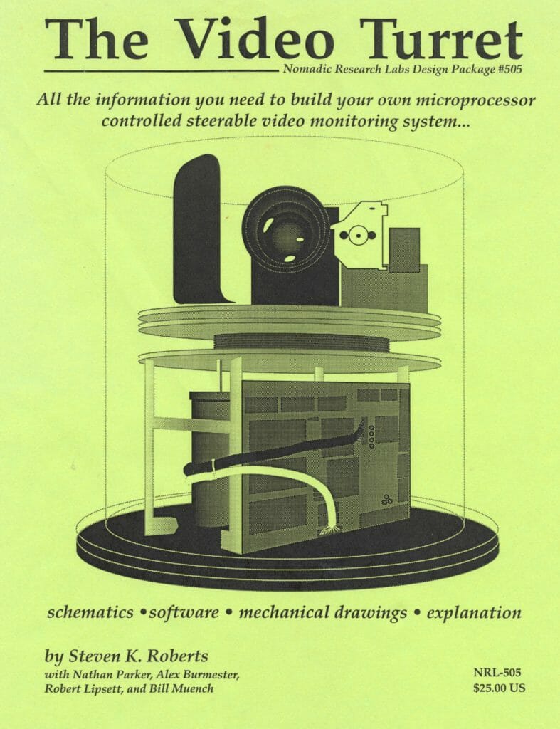
The Microship Video Turret
by Steven K. Roberts
Nomadic Research Labs
Circa 1995-1996
with:
Nathan Parker
Alex Burmester
Robert Lipsett
Bill Muench
A Bit of History
The video turret began as so many projects do — yet another one of those irrepressible wild ideas that takes on a life of its own. Somewhere in the early days of this project, it occurred to me that it might be nice to have a video camera on board. I hadn’t had much luck using a hand-held camcorder in a sealed enclosure underway (too much hassle when things get interesting), so maybe we should mount one on deck somewhere. But which way should it point? Hmmm. OK, so we’ll motorize it. Of course, it has to be sealed to handle the harsh environment… and hey, this would be great for the security system if it could see in low light… OK, so we’ll use two cameras, one color, one ultra low light B&W. Either should be able to point at any angle under software control, and scan between any pair of angles as well… at variable speed, of course. And, since the sun tends to damage things, it should be thermally protected, monitored for overheating, and provided with some sort of automatic shutter to protect the color CCD. Hey, while we’re at it, why not add a little laser, just for kicks?
Once begun, ideas like that tend to become design specifications, and that’s pretty much what happened. At the time, we were working in a lab at the University of California, San Diego — and the turret became an ideal substrate for student control engineering projects.
We quickly found out that there were some non-trivial aspects to the design, and although our mechanical engineering guru (Robert Lipsett) did a spectacular job building the physical turret, it was hard to find a student team that could get a controller working reliably. At last, nearly a year after the machining projects were completed, Nathan Parker and Alex Burmester sunk their teeth into a multitasking PWM control system design and did it beautifully. Their software, virtually unchanged, appears as the bulk of the FORTH listing below.
Shortly thereafter, we moved to a lab in Silicon Valley sponsored by Apple Computer, and in early 1996 decided to change to a flexible (zoomable) color camera and add a few other features. This led to a rather substantial packaging and refinement project, along with the addition of a servo-actuated vane (built by Ken Glaeser, visiting from UW Madison) and some of my circuitry to handle camera power, zoom, and focus controls. You can see it in use about halfway though this lovely story on KRON New Media News.
At that point, we decided to button it up and call it done, then create this document before forgetting all the key details. About 45 copies of this were sold over the next couple of years at $25 each, in the form of a fat documentation binder… now free on this page.

The turret’s two video outputs appear as channels on the video crosspoint switch, and the control front end is a graphic interface that was initially written in the venerable HyperTalk, later implemented in NewtonScript, and still later redone in Squeak. The unit is designed to be pressurized to about .5 PSI above ambient to help keep out corrosive salt air, and a minor but important addition that does not appear in this version of the documentation will be a local pressure sensor monitored by the internal control system. Also, not shown in the photos is a critically important paint job — a bright white or silver paint applied inside the cylinder, covering all surfaces except the narrow band required for camera vision. This will make the turret a lot less interesting to look at, but should keep it from becoming a solar oven on sunny days.
This article contains a lot of information: photos and notes about the design… full schematics of the control and interface hardware… listings for the code that runs it as well as the multitasker written by FORTH guru Bill Muench… comments on the HyperCard and NewtonScript front ends… mechanical drawings… and even a collection of sources for various key components.
I don’t know of any comparable commercially available video turret, although it’s easy to find little remote-controlled camera pan-tilt mounts that are pretty cool if your environmental constraints are gentle. Actually, these days many similar applications would be better served by scattering cheap video cameras around and switching among them; a complex substrate like this is becoming a bit anachronistic except in certain harsh-environment applications. In any case, there’s a good body of control and interface technique embodied here, so even if you’re not planning to copy the system you may find much of this design useful in robotics, video control, and embedded network projects.
The turret can be controlled from any terminal or computer running a vanilla communication package, but if you want to get elegant, use our ancient HyperTalk and NewtonScript front end examples as a starting point. You can now build similar graphic front end tools in the web browser.
If one were starting a project like this today, it would be sensible to use an Arduino or Raspberry Pi for the embedded micro.
Turret System Design
General
The Video Turret is a self-contained, waterproof, deck-mounted subsystem that allows either a black & white or zoomable color camera to be pointed in any direction — or swept continuously between two angles at any reasonable speed.
Packaged within a clear 8″ diameter acrylic cylinder, the turret consists of a platform driven by a 12V gearmotor. Position feedback is handled by an incremental shaft encoder, and a small sensing disc rotates at 50% of the platform speed, allowing easy end-of-travel detection via an IR optical interrupter and a hard limit switch that follows a cam. At the user end, a few basic commands allow control over this from either a text or graphic front-end: go to a specified angle, scan between two angles, set turret rotation speed, stop, or initialize.

This takes care of turret motion, but the processor has a few other activities to keep it busy as well. Control of black & white or color camera power, selection of auto or manual focus as well as driving the focus and zoom motors on the color camera, positioning a servo-controlled shutter to protect the CCD when not in use, power-controlling a small diode laser, and monitoring both temperature and pressure… all these are handled by the embedded FORTH node. Additionally, there are some reporting features that allow the Hub to collect environmental data, check the error count, look at the current turret angle and camera state, and so on.
The turret processor lives on an RS-485 (4-wire) multidrop bus running the Beeline protocol designed by Bill Muench. The specific implementation of this is not critical to turret operation, however, and other users of this design may prefer a simple point-to-point RS-232 interface as is standard with the New Micros FORTH boards. In our system, the turret is node <T>.
Physical Description
Before we discuss the control system design, a mechanical overview is in order…
DC motor (PWM controlled) is at right; quadrature shaft-position encoder is dark cylinder in center; limit-sensing disk is at upper left. There is software end-state detection with optical sensor, as well as hard cam limit that resets entire unit to prevent damage.
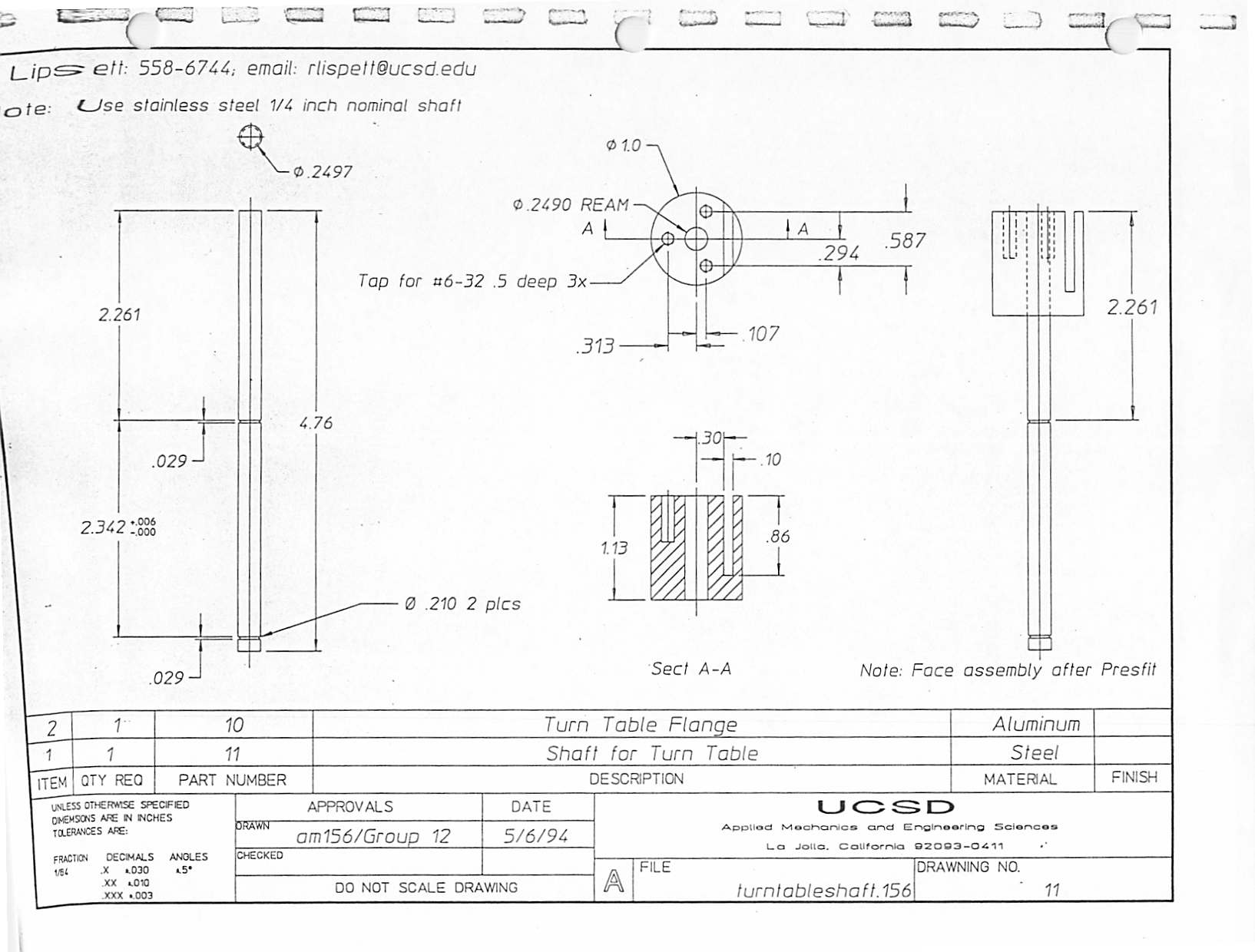
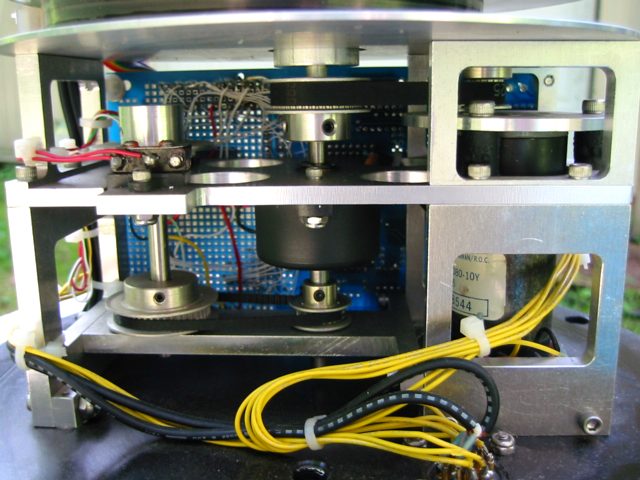
The motor (about .5 Amp at 12V peak non-stalled, 40 RPM max, 6.3 lb-in torque) is mounted on shockmounts to minimize noise, and drives the turntable shaft via a toothed belt and mating pulleys. There is a 2:1 speed ratio between motor and turntable.
The turntable shaft not only drives the platform, but also rotates the sensing disk of the position sensor (an incremental encoder from DRC). In addition, a second pair of pulleys linked by a toothed belt drives the sensing disk at an additional 2:1 speed reduction. This was required in order to accommodate the turret’s full rotation of 360 plus approximately 90 degrees, allowing either camera to smoothly sweep past any point without having to reverse and approach from the other side.
The sensing disk accommodates end-state detection through an optical pair (IR LED and phototransistor), which under normal conditions signals the software that a soft limit has been reached. The processor tracks absolute position by totalizing encoder pulses based on the direction the motor is being driven, but various errors and even belt slippage could cause drift toward a hard limit (which could damage cables). In addition, the ultimate protection is derived from a small cam-following Microswitch that rides on the edge of the same disk, blocking motor drive via hardware if something pathological is afoot and it’s trying to self-destruct. At this point, recovery is possible thanks to fortuitous placement of the two optical sensing holes… the state of the sensor immediately reveals which end state the turret is resting at, and thus which motor direction is necessary to clear it. A bit called override then bypasses the hardware limit function (yes, it is thus possible for software to crash the turret, but it’s very unlikely).
One of the more challenging aspects of the mechanical design involved cable routing. This becomes non-trivial when you think about years of rotation… careless management of cyclic flexion will destroy most cabling. The solution was a gentle spiral of 4 coax lines and a 10-conductor ribbon cable, backed with Teflon tape and captured between two plates the same diameter as the turret platform. End-to-end cycling of the turntable thus yields distributed flexion over the full length of wire.

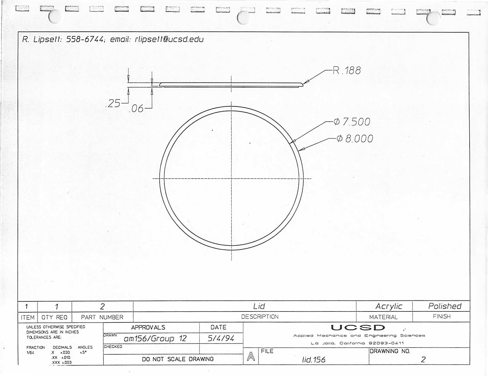
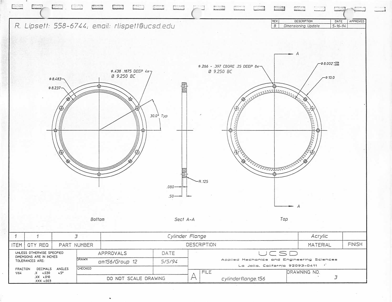
The cylindrical acrylic casing mates tightly with the baseplate, held down by eight 1/4-20 cap screws and sealed by an O-ring. The baseplate carries a sealed Amphenol military-style connector for data, power, and video… as well as two 1/8-inch NPT fittings for pressurization and differential pressure sensing (the key to waterproofing in the marine environment). These can be eliminated from more gentle terrestrial applications of this design.
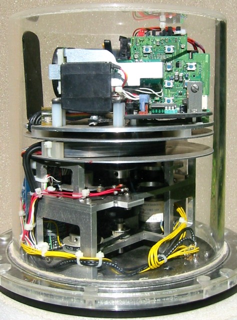
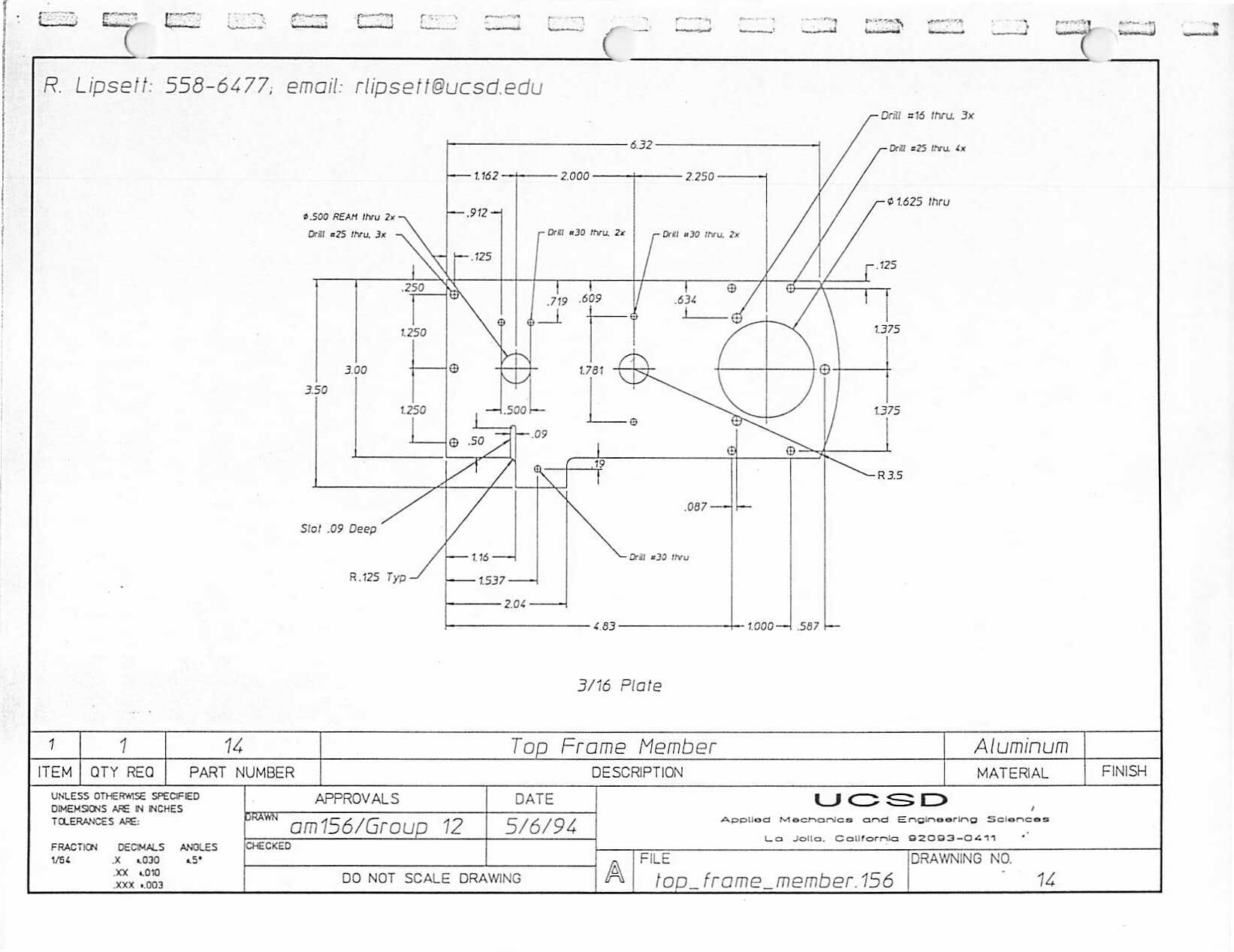
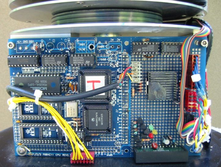
The internal machined aluminum frame also provides mounting support for the New Micros NMIT-0021 processor board that runs the show…
Circuit Description
The complete electronic design of the turret is documented in two schematic sheets:
Power Control
The power management strategy of the design is rather layered, with no less than FOUR voltage regulators. +12V power is presented to the turret via the base connector, passed onto the CPU board on the 6-pin “power” header, and regulated to +5V for the CPU by a Power Trends 78SR105 3-terminal switching regulator. This, along with the New Micros board and everything else on sheet 1 of the schematic except the PT6101 regulator, is on whenever the input +12V is applied, meaning that particular attention has to be paid to power-wasting devices in this area (intermittent loads are less critical). The RS-485 drivers on the CPU board, for example, have been changed from the original 75176 power hogs to Linear Technologies LTC485s, which are CMOS.
The HC11 has four separate power-control outputs (not including the turret motor which will be covered in the next section section): Let’s take them one at a time…
+12V
Monochrome Camera, port D4: Power-switching the monochrome camera (a GBC-200) is fairly trivial, and makes use of one of the drivers in the L293D chip that also runs the turret motor. Port D-4 is passed to the control input, with inhibit permanently tied high. It is important to note that Port D is initially an INPUT port when the 68HC11 is reset, so this line has one of the four essential 20K pulldown resistors shown next to the CPU. The switched power from the 293 is connected to one of the four coax cables through the spiral via the 6-pin “power” header, and is plugged directly into the back of the GBC camera.
+6.5V
Color Camera, port D5: This one is a little more critical. The color CCD camera requires 6.5V, from which a local +5 is generated for the NTSC combiner board via a 78M05. Also, the 6.5 is used as the source for all the color-related hardware on the turntable — the servo and the two L293Ds that handle zoom and focus.
+6.5V is generated from the main +12V bus by a Power Trends PT6101, an excellent device that is nominally +5V but allows any output voltage to be selected via the use of a single programming resistor on pin 12. In this case, 120K is the suitable value, and it physically takes the form of a 100K in series with a 20K.
The 6101 also greatly simplifies power control by providing an inhibit pin (1), that turns the device to micropower standby mode if pulled down. To be on, it must be allowed to float, not driven with a DC voltage. In the controller, this is accomplished with a pair of 2N3904s, which properly hold the inhibit pin near ground until Port D5 is configured as an output and set high.
The resulting +6.5V occupies the last pair of the 6 pins in the power header, and makes its way through the turret wire manager to the color camera… by way of the platform power switching board. On the camera, it is routed to the main DC-DC converter module and the autofocus board, and also drives a 5V 3-terminal regulator that handles the NTSC combiner and a pin on CN2808 that requires 5V.
On the platform power board, the +6.5V is immediately regulated inefficiently to +5 with yet another regulator, and this powers both of the L293D chips used for focus and zoom — as well as servo power and the 74HC04 that drives the focus/zoom control LEDs.
More on this later, but it is important to note here that the L293D parts have a huge (and to my mind, unacceptable) on-state saturation voltage, ranging from 1.2 to 1.8 volts depending on whether the switch is sourcing or sinking. Measured voltages are thus going to be below expected values in many areas — so far this has been a problem with the laser, but is more a feature than a bug in focus/zoom control since the motors are nice and slow. The generation of waste heat, however, is another and likely more critical issue.
+5V
Servo, port B6: The Futaba R/C model plane servo used to deploy and retract the shutter protecting the color CCD from direct sunlight only needs to be powered when the camera is on — and even then, only just after turn-on and just before turn-off when a brief train of suitable pulses is transmitted to set the shaft angle. To minimize wasted power otherwise, we switch servo power via Port B6 and a spare driver in the L293D associated with zooming. Again, this probably measures about 4V since the 293 is sourced from the +5V, but it seems to be stable. It would be good to confirm the operating voltage requirements of the servo over the full temperature range.
+12V
Laser, port B7 Finally, the little diode laser included primarily for amusement is switched by PB7 and the other spare driver in the L293D on the processor board (used for the turret motor and B&W camera power), passed to the laser via pin 2 of the ribbon cable. In early lab tests, this was the only device that suffered obviously from below-spec power attributable to the 293’s saturation voltage.
Had we noticed the saturation voltage issue with the L293D chips prior to fabricating the boards, the power-control drivers would have been handled differently. I would recommend that anyone cloning this system give some thought to using a logic-controlled FET switch for the simple power controls, though the ever-popular H-bridge, despite its inefficiency, greatly simplifies bi-directional motor control and minimizes parts count (it even has protection diodes). Given the low duty cycle of the motor-control operation, the loss is acceptable… but for long power-on cycles of static loads I’m not so sure.
Turret Motion Control
Speaking of motor control, most of the rest of the first page of the schematic is devoted to just that. The involved control lines are output bits PD2 and PD3, and input bits PA7, PE0, and PE1.
Basically, the FORTH motor-control code for the turret consists of two tasks running in the multitasker: Turret and PWM. These will be discussed in detail when we get to software, but basically… Turret deals with commands passed from the console, tracks the sensors, and updates variables; PWM performs pulse-width modulation by varying the OFF time of the motor according to a speed variable set by Turret. The business end of all this — consisting of the motor, driver, shaft encoder, optical limit sensor, and mechanical limit switch — is what concerns us here.
The mechanical interface hardware is all clustered on the right side of page 1 of the schematic (Turret Control). The optical encoder, an incremental DRC730 from which only one of the quadrature pulse channels is used, has its own header on the CPU board. Full quadrature operation is superfluous since the CPU already knows which direction the motor is turning and only needs feedback on the amount of rotation. (When you hook the motor up backwards, I discovered during the 6/96 repackaging project, all bets are off.) The encoder’s output is connected to PA7 on the 68HC11, which is the pulse accumulator pin. Software compares the accumulator to target values and controls the motor accordingly.
Normal mid-range operation is quite straightforward, but things get interesting at the stops. The optical stop identifies the end of travel in each direction; the mechanical stop is a hard limit that interrupts motor drive by going low and inhibiting the move bit that normally enables pin 1 of the L293D via section b of the 74HC00. The stop is also presented to the processor on PE1, invoking error-recovery code that checks the status of the optical sensor on PE0 to determine which way the motor has to be driven to escape the limit condition.
Most of the control logic is in the software, of course, but a couple of things on the schematic deserve comment. First, as noted earlier, all the Port D bits have 20K pulldowns. This is due to the bi-directional nature of the port and the fact that it wakes up as a set of inputs, allowing the connected devices to float high and the motor to wander off on its own. Second, the single 74HC00 NAND gate package handles the simple error logic mentioned a moment ago as well as drive for both sides of the motor based on a single DIRECTION bit. Finally, note that all turret motion can be disabled without affecting other subsystems by simply pulling the Motor/Limitsense header.

Microship Video Turret presentation – UCSD 1995 from Steven K Roberts on Vimeo.
Focus, Zoom, and Servo Control
The addition of the controllable color camera (replacing a small Sharp videoconferencing fixed-focus camera) introduced the possibility of much greater control over the turret images. Port B, added via a 68HC24 Port Replacement Unit, is mostly devoted to these “secondary” camera control functions.
Zoom and focus control on the camera are handled by a couple of small DC motors, which are driven by the on-board electronics via surface-mount chips labeled MM1036FF. In this application, zoom is trivial to implement — we just cut the wires from the motor and attached them to the left half of the “zoom/servo” L293D chip. Port bits PB0 and PB1 drive the part, causing the motor to move in the specified direction. A small slip clutch allows the motor to overrun the stops without damage, but it is worthwhile to make sure the bits are both reset to 0 when no active zooming is taking place. (A time-out would be good; in initial tests, the FORTH word MOOZ was used to stop the motor.)
Focus is slightly more complex since we want the camera’s autofocus function to work. The trick here was the use of both halves of an L293D, with a “FocusSel” bit (PB4) selecting one or the other via the inhibit pins, but never both — their outputs are tied together and would certainly smoke. (An inverter makes sure their states are always opposite.) When PB4 is 0, which is the default state, the camera’s autofocus motor drive output (on CN2805) is rerouted via the right half of the L293D enroute to the motor, with no net effect other than slower operation caused by the saturation voltage problem mentioned earlier.
Setting PB4 to a 1, however, disables the autofocus half of the driver and replaces motor drive with software-generated focus control (PB2 and PB3). I feared initially that it would be necessary to run dedicated wires to a momentary center-off switch to allow effective manual focus, but a simple FINEFOCUS tool in software allows a pair of keys on the Macintosh to have the same effect. Each character sets one bit or the other, holding it there for the duration of a short timing loop. The resulting jerky motion of the focus barrel is somewhat inelegant, but seems quite effective.
Focus and Zoom operation is displayed on a Dialight 555-4303 4-bit green LED package, driven by the spare sections of the 74HC04. This isn’t entirely necessary, of course, but it’s a good diagnostic for system operation and is also amusing to watch.
This is a good place to note, by the way, that long zooms through the acrylic turret yield more distortion than expected, with sharp focus impossible. The effect is not noticeable at wider camera angles.
The remaining bits of Port B are devoted to laser power switching and controlling the servo.
The servo was added to solve an expected problem with direct sunlight — we feared that parking the camera toward the sun would lead to CCD array damage. Nobody could convince us otherwise, and initially I planned to solve the problem with four phototransistors in the inside corners of an “extruded + sign,” watching them with analog input bits to see if their levels were ever above a certain threshold and, most important, equal. This would indicate that they were pointing at the sun, and evasive action would then be commanded via the Turret task.
Well, this would have been a pain, error prone, and useless if the system was powered off or hosed. The alternative was passive and simple: at all times, keep the camera lens protected by a retractable lens cap in the form of a pivoting vane, or shutter. The power-on sequence would then retract it; power-off would close it again. Ken Glaeser, visiting from Wisconsin, implemented this with a small model airplane servo and a chunk of plastic recycled from an old binder sheet lifter.
The hardware for this is rather implementation-specific, and depends on the dimensions of your camera, servo, turret head, and so on. In this case, the vertical vane measures 2.2″ wide by 3.3″ tall, and the bottom is folded at 90° and necked down to a width of about .6″. At a point roughly 2.5″ back from the bend, there is a hole, and a single bolt with jam nuts and shoulder washers serves as a pivot (mounted onto the platform). A small push-pull rod made from a scrap of .062″ aluminum links a nearby hole to one of the holes in the servo actuator — and the servo itself is mounted on four nylon standoffs. All this was assembled rather casually from scraps around the lab, and yielded a very high reward:effort ratio.
Looking back at page 2 of the schematic, the operation is simple: setting PB6 (ServoOn) applies 5V to the servo’s power lead (red) via a spare driver in the “zoom/servo ” L293D driver chip. PB5, labeled “servo,” then delivers a pulse train for about a second — 1.1ms pulses rotate the servo to the closed position; 2.6ms pulses cause it to open. At that point, servo power is turned off until the next camera power cycling operation.
Please also note that the additional I/O bits required to handle servo, laser, and zoom/focus control required the addition of a 68HC24 PRU (port replacement unit) on the New Micros circuit board. The boards come standard with a hole pattern for the PLCC socket, though it generally seems to be necessary in our systems to sand off a bit of the socket body to clear the sockets for the RS485 drivers. Most people use the RS-232 version of the 0021 board, on which this part of the board is unpopulated and thus presents no interference.
Also, we should note here that these boards are short on decoupling capacitors, though the designers thoughtfully provided a few locations for enough .1µF caps to make a difference in EMI. I recommend that you add them, and also decouple liberally in your added circuitry in the board’s kluge area.

Software Description
General
This entire discussion refers to the FORTH listings below.
The turret FORTH code fits entirely in an 8K RAM on the New Micros 68HC11 board, and takes advantage of the multitasker as noted earlier. The two motion control tasks are Turret and PWM; a third task called LED blinks the green LED according to the current status of camera power:
| 1 blink | turret alive, cameras off |
| 2 blinks | B&W camera on |
| 3 blinks | color camera on |
| 4 blinks | both cameras on |
The yellow LED indicates that the RS-485 driver is currently talking, meaning that the node is in bi-directional communication with the Hub. The LED driver connects directly to PA3 (hence the extra follower stage in the schematic at location 1-F2 — the normal LED driver loads the LTC485 control too much).
The red LED is currently available for other functions, error flag, etc.
The bulk of the turret FORTH listing consists of the motion control code, with the rest made up of power switching, zoom and focus controls, LED code, and utilities. The two sections below describe the user interface words and the internal code.
As with all the FORTH nodes, the loading procedure involves sending other essential code before the application itself. This is handled more-or-less automatically by the development scripts in Microphone II used for system development, but it’s useful to note exactly what gets transmitted from turret power-up or cold start:
- PACER — the handshaking loader used to install all remaining code
- TOOLS — various software tools and general utilities, not included here
- TASKER — the cooperative multitasker
The PACER and TASKER listings are also published in this document for the sake of completeness, but please note that despite various additions by us, they are copyrighted by Bill Muench and may not be used in commercial products without permission. For that matter, the turret code is also subject to the same restrictions, though individual non-commercial applications are fine, especially if you treat it as shareware and send us a donation to be shared with the other principal code authors (Bill Muench, Alex Burmester, and Nathan Parker).
Anyway, once these files have been loaded, the application TURRET is transmitted to the board. Since it’s a long one, a series of seven dots are echoed to the console as it loads to ease user anxiety. When the process is complete, the turret is initialized and rotates clockwise to the hardware stop, backs off a few degrees, and sits there blinking its green LED. At this point, it’s ready for operation.
User Interface FORTH Words
The subset of words in the Turret software that are of interest to the user are noted here. Directly executing any others without understanding is potentially dangerous and may cause software crashes, turret runaway, stack overflows, tasker lockup, and other pathological behavior.
As with all FORTH words in these documents, the stack notation that follows in parentheses indicates what parameters must be entered (placed on the stack) before the word itself. (Example: 45 GAZE to drive the turret to 45°)
Motion control group
- INIT ( — ) Performs setup of HC11 I/O ports, initializes variables, recalibrates turret, starts the turret tasks, and initializes the turret to the zero position by driving it to a hard limit and then backing off.
- TURSTOP ( — ) Stops the turret movement by setting WANT_TO_STOP to true and REQ_SPEED to 0. The turret task takes it from there. This is different from setting SP0, which also causes an apparent stop but does not abort any sweeping tasks in progress.
- GAZE ( degrees — ) Instructs the turret to go to the specified angle (in degrees — make sure the FORTH mode is decimal before using) at whatever speed is currently set.
- SCAN ( degrees degrees — ) Causes the turret to continuously scan between the two specified angles at whatever speed is selected. Note that the speed can be changed while the operation is underway. This will continue forever, or until a TURSTOP or INIT is executed.
- SP0, SP1, SP2, … SP9 ( — ) Sets the operating speed, from 0 (stopped) to 9 (full speed). For good video during continual scanning, speeds of 5 or less are desirable. Default is SP9, invoked upon startup.
Power Control Group
- BWON ( — ) Turns on the black & white camera by setting PD4
- BWOFF ( — ) Turns off the black & white camera
- COLORON ( — ) Turns on the color camera by setting PD 5. The resulting 6.5V power bus and its 5V subsidiary is then used to turn on the servo by setting PB6, whereupon a train of 26 ms pulses are sent to retract the shutter. Servo power is then shut off and the focus and zoom control bits are cleared.
- COLOROFF ( — ) The reverse of the above… closes the servo-controlled shutter and powers down the color camera by turning off the 6.5V power supply.
- LASERON ( — ) Turns on the diode laser by setting PB7.
- LASEROFF ( — ) Turns off the diode laser.
Zoom and Focus Control Group
- ZIN ( — ) Continuously drives the zoom motor to zoom in on objects far away. In the present implementation, this does NOT timeout automatically — execute MOOZ to stop the zoom movement.
- ZOUT ( — ) Continuously drives the zoom motor to zoom out, widening the view. As above, the motor does NOT timeout — type MOOZ to stop this action.
- MOOZ ( — ) Aborts zoom motor movement initiated by either ZIN or ZOUT.
- FINEFOCUS ( — ) Enters a loop which allows the I and O letter keys to incrementally focus in and out (far and near). Each keypress causes a small step in focus motor position. This is actually executing timed FIN and FOUT analogous to ZIN and ZOUT above, but doing that manually is impossible to control. The FINEFOCUS loop remains active permanently, or until the Q key is pressed. That event executes the internal AUTOFOCUS word to re-enable camera focus and exit the loop. If fixed manual focus is desired, don’t leave the loop (though this prevents other turret commands until the loop is quit). This is a bit of a kluge, but probably adequate for basic operation… if necessary, we can factor out the components and let the I and O keys operate at a higher level and explicitly toggle between manual and auto focus modes.
FORTH Code Internals
To keep the text section of this document readable and the listing easily updated with new versions, the full commented listing appears uninterrupted by text. The following discussions apply to the named words. This method is somewhat inconvenient, but a listing with expanded interleaved comments would be hard to keep current.
Also, please note that the first two sections of the listing are general tools, loaded (along with a few other things not needed for this application) in all FORTH nodes in the Microship network. These are NOT specific to the turret, and may or may not be relevant to other implementations. Generally, if you are building a video turret with all the same components and a minimum of reverse-engineering, it will be easiest if you load these tools before the TURRET app itself. Details are off-topic here, but some general commentary may help make sense of this…
Handshaking Pacer
This short utility is the first thing we load when transmitting software to a freshly cold-started New Micros FORTH board. It’s a handshaking loader that interacts with a script in Microphone II on the Macintosh to efficiently transfer (compile) files. The three things you need to know to interact with it at the host end are:
- Begin the transfer by sending the string NEWFILE followed by carriage return.
- Transfer the text line-by-line, waiting for control-K (^K) characters for pacing.
- Terminate the transfer by sending the string HAND and a carriage return.
Multitasker
This is Bill Muench’s cooperative time-slice multitasker, with a number of interesting features that make it particularly convenient for complex control systems… though a full discussion of the tasker is beyond the scope of this monograph.
The tasker is very easy to use for other applications if you study the turret code and reduce it to its essentials. The basic rules are:
- Execute HAT to allocate the task table
- Define each task and ACTIVATE it
- Use the PAUSE word in each task to control switching to others
- DO NOT interact with the console in any task except MAIN
- Start the tasker with COLDTASK
- Link the tasks using BUILD
- View active tasks using TASKS
- Unload active tasks using RESETTASKER
- Use GET and RELEASE for semaphore resource-locking
The tasker is Copyright 1990 by Bill Muench, all rights reserved. He freely allows personal, non-commercial use, but any commercial application MUST be contractually arranged with him.
The remainder of this section describes the code specific to the video turret…
Variables and General Words
The first section of the listing consists of constants and variables, most of which need little elaboration. Much of the following commentary is extracted from the report on the turret control system by Parker and Burmester…
- TRUE and FALSE are defined as constants because the word NOT in FORTH is a bitwise not.
- MAX_ANG is the number of pulses emitted by the optical encoder between the two optical stops (about 450 degrees).
- SPEED_SLOW is used as the slow speed to move when approaching the stopping point to prevent overshoot.
- ON_PULSE is the motor on time that can be adjusted to fine-tune the speed range of the motor. Increasing this will make the motor go faster.
- OFF_MULT is another constant that can be adjusted to tune the motor speed. Its value is multiplied by the inverse of the current speed to yield the number of off-clicks. Increasing this value will expand the available speed range in the slower direction (i.e., it will make SP1 slower).
The various port constants that follow are fairly obvious — they just define the port addresses and bit masks used in the 68HC11. In the current version of the listing, another group of more recently-added constants for focus, zoom, and power control appears near the end of the listing with the “experimental” code.
At the end of the constant group are the Task Table builders… the 0 0 0 in each tells the tasker to use the default value (10) for stack depth, return stack depth, and variable space allocated to each task.
Within the variables, there are three that should be checked by the Hub periodically. These are:
- TIME_OUT_REACHED
- MECHSTOP_OVERRUNS
- OPTSTOP_OVERRUNS
The first two indicate serious errors; the last is expected to occur often, but is useful as an indication of the turret’s recalibration efforts.
The groups labeled PORT READERS and PORT SETTERS are the low-level words that interface directly with the hardware.
Turret Task
- MECH_OVRD is the first word defined in the turret task , and deals with the critical function of recovering from hitting the mechanical stop. Ideally, it should only be used during initial power-up calibration of the turret.
- OPT_OVRD is used when the optical stop is hit. It moves off the sensor and recalibrates itself.
- CHECK_STOPS is called in the main turret task loop to make sure the turret is not hitting any stops.
- SLOWDOWN_STOP is executed whenever a new angle is received. Rather than abruptly change direction and lose accuracy of the position due to the motor’s momentum, Parker & Burmester chose to gently stop so the internal position may be updated. Once stopped, the new direction is set and control is returned to the main turret task loop.
- TUR_TASKGO is the main turret task. It is basically a big loop that first checks for a new command and processes it if there is one. Second, it checks the stops. Third, it sets the current speed and slows down if we are getting near the destination. Finally, it swaps the angles if we are in sweep mode.
PWM Task
- PWM_TASKGO is short and easy to follow. It simply turns on the motor in one loop and turns it off in the next.
Setup Words
- SET_SPEED is no longer used because we discovered that parsing the argument to this command took so long that the turret noticeably jerked. It is used for manual debugging purposes only.
- SETUP_PORTS is crucial upon startup. The 68HC11 defaults to having Port D as an input, and we need the pins for outputs.
- SETUP_TURRET is needed for calibration before accepting any commands. It rotates all the way clockwise until both optical and mechanical stops are triggered. It then rotates CCW until it passes the optical stop. At this point the position of the turret is known and we can start accepting commands.
- COLD_TUR builds the two tasks in the above code and sets them up to be run under the multitasker.
- INIT (after the intervening LED, servo, power, and zoom/focus code) is the routine that runs on startup so that the ports are set properly, variables are initialized, tasks are started, and the turret is calibrated.
LED Power Monitor
The next group of words is involved with a little task that reports on power status by blinking the green LED as specified in the table above. The LED FLASHER TIMING words just define blink intervals for the following key word:
- BLINKY invokes two port reads with BW_ON? and COLOR_ON?, each of which returns a bit corresponding to the actual power control bit on Port D. These are rotated into position such that when added to each other +1, the B&W camera contributes one blink and the color contributes two. The +1 causes a single blink even if neither camera is on.
Power and Servo Controls
- COL_PWRON and COL_PWROFF are the raw turnon and turnoff of the color camera, not including servo movement.
- COLORON and COLOROFF add a burst of timed pulses to the RC model servo after powering the color camera on and before powering it off. The key words are CLOSE and OPEN, which use the preceding timing and bit-banging words to deliver pulse trains of 1.1 ms high and 100ms low for the closure; 2.6 ms high and 100 ms low for the opening. The count of a mere 30 pulses was determined empirically, and is sufficient to rotate the servo into the desired positions.
Zoom and Focus Controls
Using the H-bridge motor-control chips on the turret head, the following words not otherwise discussed in Section 4.2 handle rotation of the camera’s lens motors:
- AUTOFOCUS sets internal camera focus mode by disabling the port bits PB2 and PB3.
- INFOCUS and OUTFOCUS are analogous to ZIN and ZOUT, but for the focus motor.
Front End Software
The direct text interface to the video turret is easy enough to use, but in this point and click era it does seem a bit primitive. The design philosophy of the whole Microship control system is based on the separation between busy I/O-intensive distributed processors (with cryptic command syntax) and the graphic front-end systems which appear throughout the ship on Macintosh computers. For this application, we initially chose HyperCard back in 1995, due to the powerful scripting tools available in the HyperTalk language.
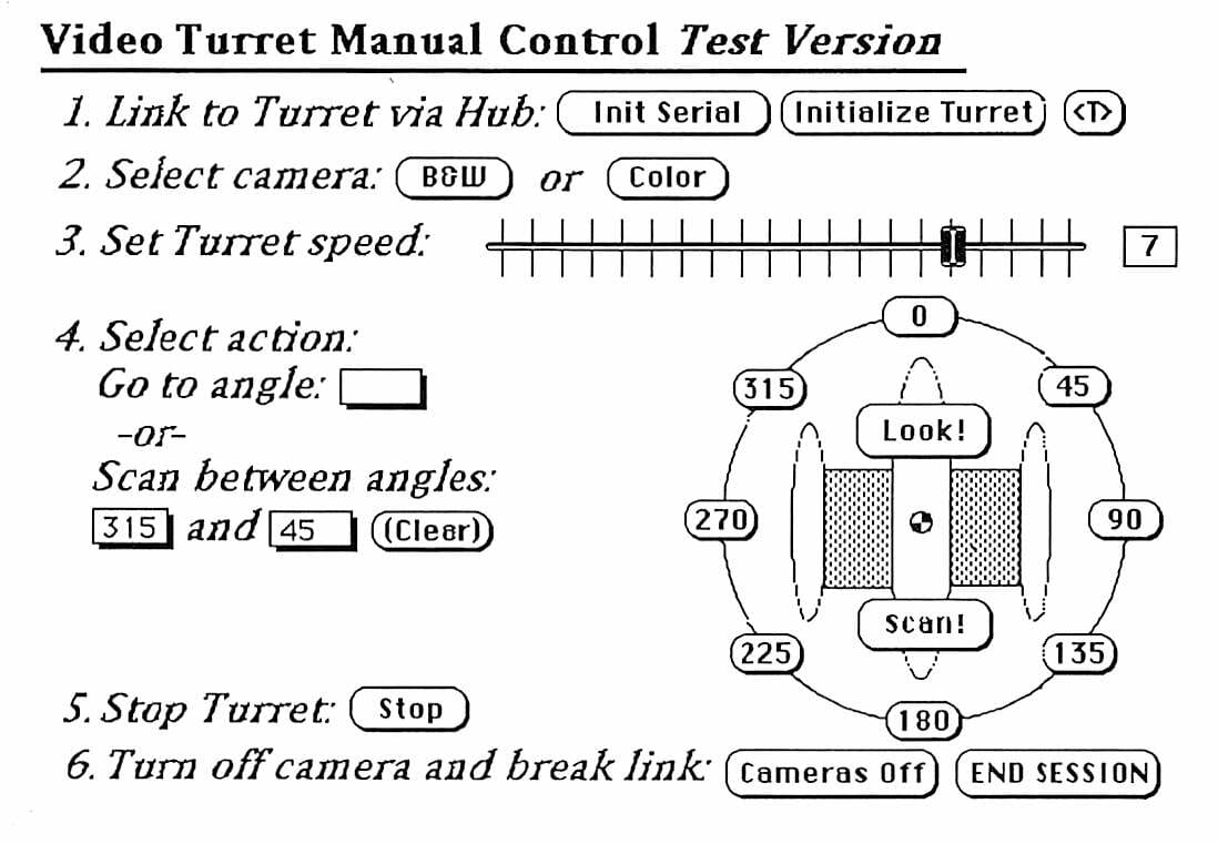
This reduces turret operation to a rather intuitive process (as long as you can think in terms of degrees, ignore the fact that the two cameras are 90° apart, understand the subtleties of initiating and terminating a network connection, and can look at the turret to get visual feedback that it’s working!). In other words… there was little more to this UI than simple buttons that generate one-line FORTH commands, such as this trivial example that turns on the color camera:
•-•-•-• BUTTON: card button "Color"
on mouseUp
get CommConnect (“send”,CAM_A_ON & Return)
put “COLORON” into msg
end mouseUp
Or, somewhat less trivially, the command to direct the turret’s gaze to a particular angle when the “Look!” button is pressed:
•-•-•-• BUTTON: card button "Look!"
on mouseUp
global angle_1, angle_2
put angle_1 into card field “goto_angle”
put empty into card field “angle_1”
put empty into card field “angle_2”
put angle_1 && GAZE into msg
get CommConnect (“send”, angle_1 && GAZE & Return)
put empty into angle_1
end mouseUp
As I mentioned earlier, however, the HyperCard front end didn’t last very long… we soon moved to a wireless network based on the excellent Tarpon, by Digital Ocean… a ruggedized industrial Newton with a 900 MHz wireless connection to the host Mac. This was considerably sexier:
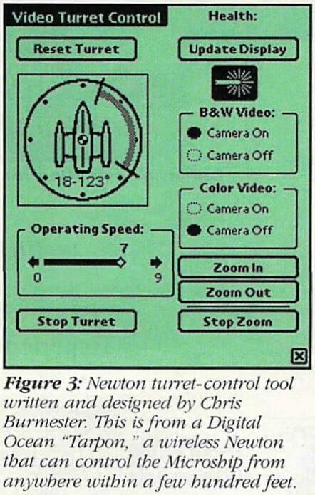
The bulk of the design of this elegant software was done by Chris Burmester, aided by Erik Browne… and I even had a go at NewtonScript development before the product line was canceled and we were back to the UI drawing board once again.
PRODUCT SOURCES
| The following are pointers, some doubtless dated by now, to various special or hard-to-find components. We do not detail chips, connectors, discretes, stainless hardware, stock aluminum, etc.
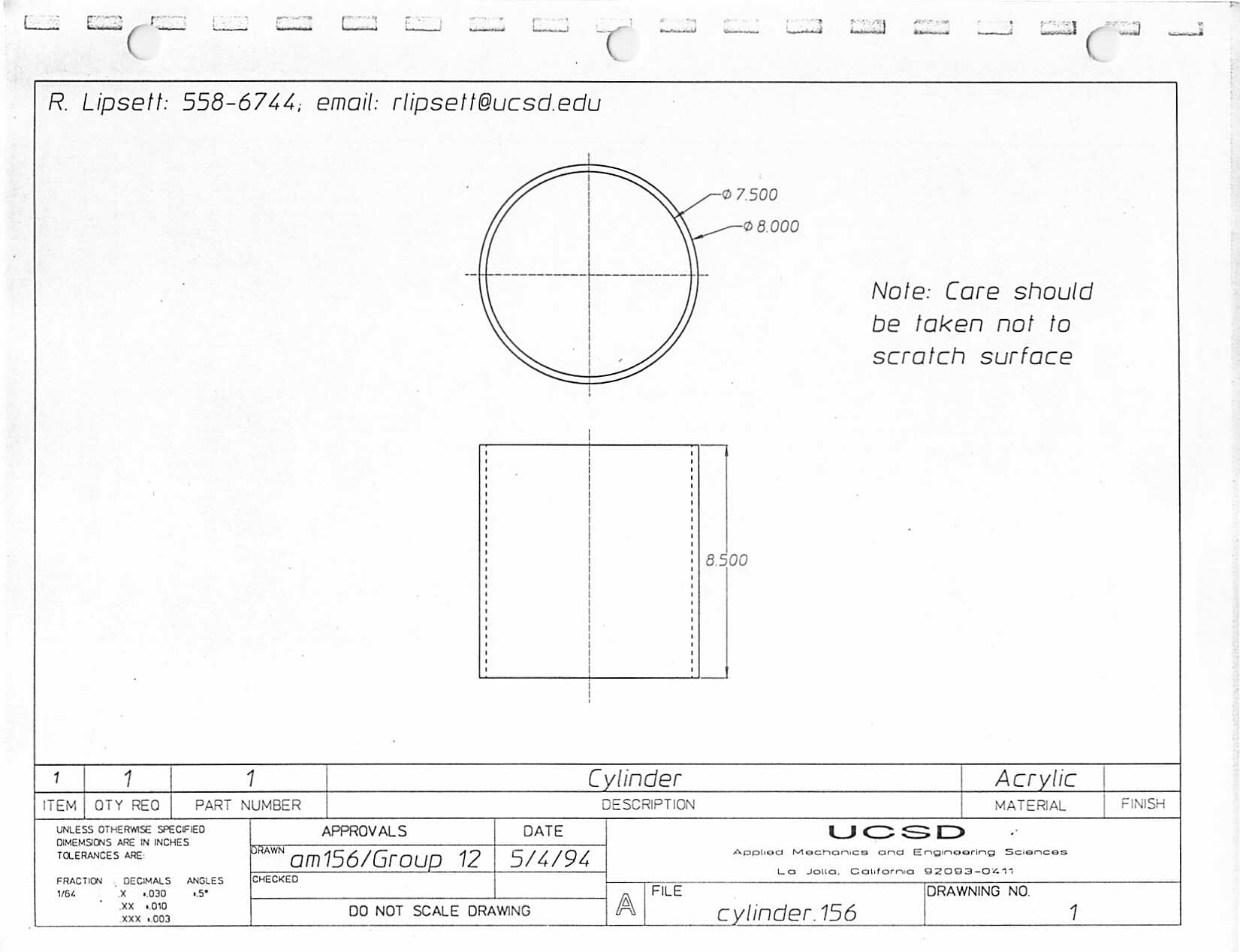
Turret drive motor: 12VDC, .5A, 40RPM reversible gear motor, model TM89MTR5700. $17.50 in 1994 from Herbach & Rademan, 18 Canal Street, PO Box 122, Bristol, PA 19007-0122. 800-848-8001. Acrylic Cylinder: 8″ OD. Ridout Plastics, 5535 Ruffin Road, San Diego, CA 92123. 619-560-1551. Pulleys and Belts: Stock Drive Products, 2101 Jericho Turnpike, PO Box 5416, New Hyde Park, NJ 11042-5416. 516-326-3300. PTFE Tape for cable spiral: Type 3M5430 from Hughes RS Co., 9693 Distribution Ave., San Diego, CA. 619-578-9880. Shaft Position Encoder: Model 730 incremental optical, from Dynamic Research Corp, Encoder Division, 60 Concord St., Wilmington, MA 01887-2193. 617-658-6100. 68HC11 FORTH Control Board: The NMIT-0021 is part of a very broad line of low-cost, easy-to use controllers and I/O hardware from New Micros, 1601 Chalk Hill Road, Dallas, TX 75212. 214-339-2204. R/C Servo: Futaba, from any good radio-control model shop. 78SR105 and PT6101 Switching Regulators: These spectacular parts make linear 3-terminal regulators obsolete. Power Trends, 1101 North Raddant Road, Batavia, IL 60510. 800-531-5782. http://www.powertrends.com/isr/ Diode Laser, headers, connectors, small parts: Halted Specialties, 3500 Ryder St., Santa Clara, CA 95051. This is far and away the coolest geek store in Silicon Valley. |
ACKNOWLEDGMENTS
The video turret was a complex project that required over a year of development. The following list of contributors opens with the key designers and programmers…
Key participants
Robert Lipsett — mechanical design and fabrication of turret
Bruce Thomas and crew — machining of structural components
Nathan Parker — motion control hardware and software
Alex Burmester — motion control hardware and software
Bill Muench — multitasker and multidrop software
Ken Glaeser — fabrication of servo-controlled shutter
Steven K. Roberts — concept, power control, electronic fab, final code
Minor Participants
Steve Porter — Mechanical Engineering consulting
John Powell — Mechanical Engineering consulting
Clark Guest — Electrical Engineering consulting
Mark Moorcroft — servo applications assistance
San Le — assistant to Robert Lipsett
Eduardo Garcia — early motion control attempts
Ray O’Neill — early motion control attempts
Ophira Bergman — early motion control attempts
Equipment Donors
George Martin — color camera
UCSD ME Dept and machine shop — machining and hardware
Applied Ocean Physics — 6″ cylinder (not used)
Halted Specialties — shaft-position encoder and diode laser
Power Trends — switching regulators
Linear Technologies — RS485 drivers
New Micros — 68HC11 FORTH processor board
FORTH LISTINGS
File-Transfer Pacer and Host Script
( PACER.NMI )

FORGET TASK

HEX

: \ ( -- ) #TIB @ >IN ! ; IMMEDIATE

: read ( a u -- u ) ( no echo )
 OVER + OVER ( a end start )
 BEGIN 2DUP XOR ( end of buffer ? )
 WHILE KEY  DUP 0D = ( end of line ? )
 IF DROP  MIN DUP ( yes, exit )
 ELSE  BL MAX  OVER C!  1+ ( no, buffer char )
 THEN ( and convert whitespace to blank )
 REPEAT DROP  SWAP - ;

: HAND ( -- ) -1 >IN ! ; ( signal end of file )

: NEWFILE ( -- ) ( like QUIT )
 BEGIN TIB @ C/L  ( start pacing ) 0B EMIT  read #TIB !
 0 DUP >IN ! BLK !  INTERPRET  >IN @ 0< ( end of file ? )
 UNTIL [COMPILE] \ ;

CREATE B.TOOLS ( marker )

( Copyright 1990 Bill Muench All rights reserved. )
 ( Bee's file transfer protocol )
 ( 940124 update for 3.5E )

Host script (Microphone II) to interact with above pacer:

1   Set Variable * FORTHFILE from File Dialog "'Protocol transfer FORTH file?'"
 2   Send Text String "'NEWFILE^M'"
 3   Send File * Text Line by Line "FORTHFILE"
 4   Repeat
 5    Wait for Text in Stream "'^K'"
 6    Send Line *
 7   Until Failure
 8   Send Local to Screen "'FORTH file transfer complete ^M' "
 9   Send Text String "'HAND^M' "

(Begin by transmitting the PACER itself to the FORTH board open-loop, waiting .5 sec after each line.  Then use script to transfer subsequent files.)

Multitasker

CR .( TASK.NMI  cooperative multitasker )
 ( .)
 CR .( Copyright 1990 Bill Muench All rights reserved. )
 ( .)
 ( 940224 code executive )
 ( 940124 update for NMI Forth 3.5E )
 ( 960703 update to add RESETTASKER )

( only MAIN task may use ?TERMINAL KEY EMIT )
 ( tid means task indentifier )
 ( tid=u/s/r may be in ROM )
 ( tid has pointers to RAM for user area, data stack, return stack )
 ( 3.5E MAIN  w/ip/up/user/--<pad/tib>--<r--<s )
 ( minimal task  user/12/--/16/--<s--/24/--<r )

FORTH DEFINITIONS

CREATE B.TASK ( marker )

( ========================================================== )

DECIMAL

0 USER STATUS ( either PASS or WAKE )
 2 USER FOLLOWER ( next task's STATUS )
 4 USER TOS ( top of stack on entry )
 6 USER U1 ( free )

( ========================================================== )

HEX

0B7E CONSTANT PASS ( sev  jmp FOLLOWER )
 AD00 CONSTANT WAKE ( 0 ,x jsr  FOLLOWER )

\ CODE wake ( -- ) ( start next task )
 \   pulx                  ( addr = FOLLOWER )
 \   dex dex  up stx       ( user base -> STATUS )
 \   TOS STATUS - ,x lds   ( restore rp from TOS )
 \   puly                  ( restore sp )
 \   pulx  inx inx  ip stx ( restore ip )
 \   0 ,x ldx  w stx       ( save cfa in working 'reg' )
 \   0 ,x ldx  0 ,x jmp    ( ITC next )
 \ END-CODE

\ CODE PAUSE ( -- ) ( allow another task to execute )
 \   ip ldx  pshx             ( save ip )
 \   pshy                     ( save sp )
 \   up ldx                   ( user base )
 \   TOS STATUS - ,x sts      ( save rp in TOS )
 \   FOLLOWER STATUS - ,x ldy ( FOLLOWER = next task )
 \   ' wake CFA @ ## ldx      ( setup for WAKE = 0 ,x jsr )
 \   0 ,y jmp                 ( jump task table )
 \ END-CODE

( ========================================================== )

CODE wake ( -- )
 38 C,        ( pulx )
 9 C,        ( dex )
 9 C,        ( dex )
 DF C,   4 C, ( 4 stx )
 AE C,   4 C, ( 4 ,x lds )
 18 C,  38 C, ( puly )
 38 C,        ( pulx )
 8 C,        ( inx )
 8 C,        ( inx )
 DF C,   2 C, ( 2 stx )
 EE C,   0 C, ( 0 ,x ldx )
 DF C,   0 C, ( 0 stx )
 EE C,   0 C, ( 0 ,x ldx )
 6E C,   0 C, ( 0 ,x jmp )
 END-CODE

CODE PAUSE ( -- )
 DE C,   2 C,          ( 2 ldx )
 3C C,                 ( pshx )
 18 C,  3C C,          ( pshy )
 DE C,   4 C,          ( 4 ldx )
 AF C,   4 C,          ( 4 ,x sts )
 1A C,  EE C,   2 C,   ( 2 ,x ldy )
 CE C,  ' wake CFA @ , ( ' wake CFA @ ## ldx )
 18 C,  6E C,   0 C,   ( 0 ,y jmp )
 END-CODE

( ========================================================== )

: 'S ( tid a -- a ) ( index another task's local variable )
 STATUS - SWAP @ + ; ( PASS  TASK1 STATUS 'S  ! )

: AWAKE ( tid -- ) WAKE SWAP STATUS 'S ! ; ( wake another task )
 : SLEEP ( tid -- ) PASS SWAP STATUS 'S ! ; ( sleep another task )

: ACTIVATE ( tid -- )
 DUP 2+ 2@        ( tid sp rp )
 2- R> OVER !     ( save ip on rp and setup exit )
 2- SWAP OVER !   ( save sp on rp )
 1- OVER TOS 'S ! ( save rp-1 in tos )
 AWAKE ;

: STOP ( -- ) PASS STATUS ! PAUSE ; ( sleep current task )
 : COMA ( -- ) BEGIN STOP AGAIN ;
 : HALT ( tid -- ) ACTIVATE COMA ;

( shared resources ========================================= )

( a simple semaphore is just a VARIABLE )

: GET ( semaphore -- )
 PAUSE  DUP @ STATUS XOR ( owner? )
 IF BEGIN DUP @ WHILE PAUSE REPEAT ( no, wait for release )
 STATUS SWAP ! ( lock ) EXIT
 THEN DROP ;

: RELEASE ( semaphore -- )
 DUP @ STATUS XOR IF DROP EXIT THEN  0 SWAP ! ( unlock ) ;

( ========================================================== )

: HAT ( u s r "name" -- ) ( -- tid )
 CREATE HERE >R 6 ALLOT  RAM HERE R@ ! ( user )
 >R + 01C + ALLOT HERE ( user/12/--</16/sp)
 R> 018 + ALLOT HERE ( --</24/rp )  R> 2+ 2! ;

: BUILD ( tid -- ) ( sleep and link new task )
 DUP 2@ SWAP OVER - 0BB FILL ( debug tracer )
 DUP SLEEP  DUP @ ( u ) >R  2+ 2@ ( s r )
 R@ [ R0 STATUS - ( offset ) ] LITERAL + 2! ( r0 s0 )
 FOLLOWER @  R@ FOLLOWER !  R> 2+ ! ( links ) ;

( ========================================================== )

CREATE MAIN  4 ( UP ) @ , S0 @ , R0 @ , ( point to the NMI defaults )

: RESETTASKER ( -- ) ( remove all TID from tasker )
 6 4 ! ( default user base address )
 STATUS FOLLOWER ! ( init FOLLOWER )
 MAIN AWAKE  ( should always be awake )
 [ ' PAUSE CFA ] LITERAL 'PAUSE ! ( set PAUSE vector ) ;

RESETTASKER

( ========================================================== )

: TASKS ( -- ) ( display status of all currently linked tasks )
 BASE @  STATUS  DUP
 BEGIN CR 2+ @  DUP HEX 6 U.R SPACE ( next status addr )
 DUP @ WAKE XOR IF ." PASS" ELSE ." WAKE" THEN
 ."  depth="  2DUP =
 IF DEPTH
 ELSE DUP [ S0 STATUS - ( offset ) ] LITERAL + @
 OVER [ TOS STATUS - ( offset ) ] LITERAL + @ 1+ @ -  2/
 THEN DECIMAL 0 .R  2DUP =  NUF? OR
 UNTIL 2DROP  BASE ! CR
 ;

: .TID ( tid -- ) ( display the task table )
 2@ SWAP OVER - DUMP ;

( ========================================================== )

Turret Control Software

.( Transmitting video turret software )

\ VIDEO TURRET CONTROL SOFTWARE
 \ NATHAN PARKER, ALEX BURMESTER  (C) 1995
 \ and Steve Roberts, Nomadic Research Labs  (c) 1996

FORTH DEFINITIONS
 CREATE B.TURRET

HEX

\  ***** CONSTANTS *****

-1    CONSTANT    TRUE
 0    CONSTANT    FALSE

\ MAX ANGLE (CLICKS)
 E9    CONSTANT MAX_ANG
 19F    CONSTANT MAX_DEG

\  MAX SPEED + 1 (0 IS STOP, 9 IS FULL SPEED)
 0A    CONSTANT MAX_SPEED

\ A SLOW SPEED TO GO WHEN SLOWING DOWN
 3    CONSTANT SPEED_SLOW
 0    CONSTANT SPEED_STOPPED

\ ON TIME: LENGTH IN TICKS OF ON-PULSE
 40    CONSTANT ON_PULSE

\ OFF PULSE MULTIPLIER (INCREASE TO MAKE 0-9 RANGE SLOWER)
 01    CONSTANT OFF_MULT

\ NUM OF PULSES FROM DESTINATION TO START SLOWING DOWN
 \ 7    CONSTANT SLOWDOWN_WIDTH

\ TIMEOUT VALUE (SHOULD BE REALLY LARGE)
 2000    CONSTANT TIME_OUT

.( . )
 \  ***** PORT CONSTANTS *****
 \ DATA DIRECTION REG  PORT D
 B009    CONSTANT DDRD
 3C    CONSTANT DDRD_MASK

B004    CONSTANT    PORT_B

\ PORT E BIT #0 INPUT -- "OPTICAL STOP"
 B00A    CONSTANT OPTSTOP_PORT
 01    CONSTANT OPTSTOP_MASK

\ PORT E BIT #1 INPUT -- "MECHANICAL STOP"
 B00A    CONSTANT MECHSTOP_PORT
 02    CONSTANT MECHSTOP_MASK

\ PORT A BIT #7 INPUT -- PULSE ACCUMULATOR "OPTICAL ENCODER"
 B027    CONSTANT PA_PORT           \ PA COUNT VALUE (R/W)
 B026     CONSTANT PAC_PORT          \ PA CONTROL PORT
 0F    CONSTANT PAC_AND_MASK      \ PA CONTROL REG "AND-MASK"
 40    CONSTANT PAC_OR_MASK       \ PA CONTROL REG "OR-MASK"

\ PORT A BIT #6 OUTPUT -- "OVERRIDE"
 B000    CONSTANT OVRD_PORT
 40    CONSTANT OVRD_MASK
 BF    CONSTANT OVRD_MASK_N

\ PORT D BIT #2 OUTPUT -- "DIRECTION"
 B008    CONSTANT DIR_PORT
 04    CONSTANT DIR_MASK
 FB    CONSTANT DIR_MASK_N

\ PORT D BIT #3 OUTPUT -- "MOVE"
 B008    CONSTANT MOVE_PORT
 08    CONSTANT MOVE_MASK
 F7    CONSTANT MOVE_MASK_N

\ PORT D BIT #4 OUTPUT -- "B&W POWER"
 B008    CONSTANT PORT_D
 10    CONSTANT BW_MASK
 EF    CONSTANT BW_MASK_N

\ PORT D BIT #5 OUTPUT -- "COLOR POWER"
 20    CONSTANT COLOR_MASK
 DF    CONSTANT COLOR_MASK_N

\  **** TASK TABLES ****
 0 0 0 HAT  PWM_TASK
 0 0 0 HAT  TUR_TASK
 0 0 0 HAT  LED_TASK

.( . )
 \  **** VARIABLES ****

VARIABLE SPEED_CUR          \ CURRENT SPEED
 VARIABLE ANG_CUR

VARIABLE ANG_A1
 VARIABLE ANG_B1
 VARIABLE ANG_A2
 VARIABLE ANG_B2
 VARIABLE NEW_CMD
 VARIABLE IS_STOPPED
 VARIABLE REQ_DIST
 VARIABLE REQ_SPEED

VARIABLE WANT_TO_STOP

VARIABLE MECHSTOP_OVERRUNS
 VARIABLE OPTSTOP_OVERRUNS
 VARIABLE TIME_OUT_REACHED

\  **** CONSOLE WORDS ****

: SP0 0 REQ_SPEED ! 1 NEW_CMD ! ; ( -- )
 : SP1 1 REQ_SPEED ! ; ( -- )
 : SP2 2 REQ_SPEED ! ; ( -- )
 : SP3 3 REQ_SPEED ! ; ( -- )
 : SP4 4 REQ_SPEED ! ; ( -- )
 : SP5 5 REQ_SPEED ! ; ( -- )
 : SP6 6 REQ_SPEED ! ; ( -- )
 : SP7 7 REQ_SPEED ! ; ( -- )
 : SP8 8 REQ_SPEED ! ; ( -- )
 : SP9 9 REQ_SPEED ! ; ( -- )

: TURSTOP 0 REQ_SPEED ! TRUE WANT_TO_STOP ! ; ( -- )

: ANGLE_TRANS ( N -- N )    \ TRANS FROM DEGREES CW TO PULSES CCW
 MAX_DEG SWAP -
 MAX_ANG MAX_DEG */
 ;

: SCAN ( N1 N2 -- )   \ need to add angle conversion
 ANGLE_TRANS
 ANG_A1 !
 ANGLE_TRANS
 ANG_B1 !
 1 NEW_CMD !
 ;

: GAZE ( N1 -- )
 ANGLE_TRANS
 DUP
 ANG_A1 !
 ANG_B1 !
 1 NEW_CMD !
 ;

.( . )

\  **** PORT READERS ****
 \ RETURNS STATE OF THE OPTICAL STOP SENSOR  ( -- ? )
 \ NORMALLY FALSE
 : GET_OPTSTOP OPTSTOP_PORT C@ OPTSTOP_MASK AND 0= NOT ;

\ RETURNS STATE OF THE MECHANICAL STOP SENSOR ( -- ? )
 \ NOTE: MECHSTOP IS NORMALLY _TRUE_ (LIKE, IT'S OK TO GO)
 : GET_MECHSTOP  MECHSTOP_PORT C@ MECHSTOP_MASK AND 0= ;

\ RETURNS VALUE OF PULSE ACCUMULATOR ( -- C )
 : GET_PA  PA_PORT C@ ;

\ RETURNS THE CURRENT DIRECTION (T-CW, F-CCW)  ( -- ? )
 : GET_DIR  DIR_PORT C@ DIR_MASK AND 0=  ;

\  **** PORT SETTERS ****
 \ CLEAR THE PULSE ACCUMULATOR  ( -- )
 : CLR_PA 0 PA_PORT C! ;

\ SET DIR TO CCW (LOW)  ( -- )
 : DIR_CCW   DIR_PORT C@ DIR_MASK OR DIR_PORT C! ;
 : L DIR_CCW ;

\ SET DIR TO CW (HIGH)  ( -- )
 : DIR_CW  DIR_PORT C@ DIR_MASK_N AND DIR_PORT C! ;
 : R DIR_CW ;

\ SETS THE DIRECTION (T-CW, F-CCW)  ( ? -- )
 : SET_DIR   IF DIR_CW ELSE DIR_CCW THEN ;

\ SET MOVE TO TRUE (START THE MOTOR)  ( -- )
 : MOVE_ON  MOVE_PORT C@ MOVE_MASK OR MOVE_PORT C!     ;
 : G MOVE_ON ;

\ SET MOVE TO FALSE (STOP THE MOTOR)  ( -- )
 : MOVE_OFF    MOVE_PORT C@ MOVE_MASK_N AND MOVE_PORT C! ;
 : S MOVE_OFF ;

\ SET MOVE TO ON OR OFF (T OR F)  ( ? -- )
 : SET_MOVE  IF MOVE_ON ELSE MOVE_OFF THEN ;

\ **** GENERAL WORDS ****

: SWAP_VAR      ( A1 A2 -- )
 2DUP        ( A1 A2 A1 A2)
 @           ( A1 A2 A1 N2 )
 2SWAP       ( A1 N2 A1 A2 )
 SWAP
 @           ( A1 N2 A2 N1 )
 SWAP !
 SWAP !
 ;

.( . )

\ ##### TURRET TASK #####

\ PULSE THE OVERRIDE OUTPUT -- DO WHEN YOU HIT THE MECH STOP   ( -- )
 \ THIS IS VERY IMPORTANT CODE!
 : MECH_OVRD
 GET_MECHSTOP IF     \ SO WE CAN'T SCREW IT UP IF WE'RE NOT ON THE MECH STOP
 GET_OPTSTOP IF      \ MAKE SURE WE GO _BACK_ FROM WHERE WE CAME
 DIR_CCW
 ELSE
 DIR_CW
 THEN

OVRD_PORT C@ OVRD_MASK OR OVRD_PORT C! \ TURN ON THE OVERRIDE
 SPEED_SLOW SPEED_CUR !        \ GO!
 BEGIN
 PAUSE
 GET_OPTSTOP GET_MECHSTOP OR
 WHILE REPEAT            \ ... UNTIL WE'RE OFF THE MECH/OPT STOPS

OVRD_PORT C@ OVRD_MASK_N AND OVRD_PORT C! \ TURN OFF THE OVERRIDE
 BEGIN
 PAUSE
 GET_OPTSTOP NOT
 WHILE REPEAT            \ ... UNTIL WE HIT THE NEXT OPTSTOP (SOON)
 BEGIN
 PAUSE
 GET_OPTSTOP
 WHILE REPEAT            \ ... UNTIL WE'RE OFF THE OPTSTOP

CLR_PA                  \ START COUNTING PULSES HERE
 SPEED_STOPPED SPEED_CUR !  \ NOW WE'RE IN THE GOOD PLACE
 10 0 DO PAUSE LOOP      \ WAIT TILL WE'RE ACTUALLY STOPPED

GET_DIR
 IF
 MAX_ANG GET_PA - ANG_CUR !  \ RESET OUR POSITION
 ELSE
 GET_PA ANG_CUR !
 THEN
 CLR_PA
 THEN
 ;

: OPT_OVRD     \ GET OFF AN OPTICAL STOP, RESET ANG_CUR
 GET_OPTSTOP IF
 GET_DIR IF      \ REVERSE OUR DIRECTION
 DIR_CCW
 ELSE
 DIR_CW
 THEN

SPEED_SLOW SPEED_CUR !  \ GO!
 BEGIN
 PAUSE
 GET_OPTSTOP NOT GET_MECHSTOP OR
 UNTIL            \ ... UNTIL WE GET OFF THE OPT STOP

CLR_PA
 SPEED_STOPPED SPEED_CUR !  \ STOP
 10 0 DO PAUSE LOOP      \  ... AND WAIT TILL WE REALLY STOP

GET_DIR IF              \ RESET OUR POSITION
 MAX_ANG GET_PA - ANG_CUR ! \ .. FROM LEFT SIDE
 ELSE
 GET_PA ANG_CUR !    \  .. FROM RIGHT SIDE
 THEN
 CLR_PA

GET_MECHSTOP IF         \ IN CASE WE GOT SCREWED UP
 MECH_OVRD
 THEN

THEN
 ;

: CHECK_STOPS ( -- ? )     \ see if we have hit any stops, DEAL WITH THEM

GET_MECHSTOP          \ ARE WE ON MECH STOP?
 IF
 0 SPEED_CUR !
 MECHSTOP_OVERRUNS 1+!
 MECH_OVRD        \ get off the mechanical stop.  -- RESETS ANG_CUR
 TRUE
 ELSE
 FALSE
 THEN

GET_OPTSTOP
 IF
 0 SPEED_CUR !
 OPTSTOP_OVERRUNS 1+!
 OPT_OVRD        \ get off the optical stop.  -- RESETS ANG_CUR
 TRUE
 ELSE
 FALSE
 THEN

OR      \ RETURN TRUE IF WE HIT SOMETHING
 ;

\ Slowdown, stop, then read new command.
 : SLOWDOWN_STOP     ( -- )
 SPEED_CUR @ SPEED_STOPPED = NOT
 IF          \ WERE WE MOVING?
 SPEED_CUR @ SPEED_SLOW >
 IF      \ GOING TOO FAST?
 SPEED_CUR @ 2 /             \ (HOW FAR TO DRIFT)
 SPEED_SLOW SPEED_CUR !      \  ... SLOW DOWN
 ELSE
 2                           \ (HOW FAR TO DRIFT)
 THEN

GET_PA +     \ WHERE TO DRIFT TO
 BEGIN
 PAUSE
 DUP GET_PA <                \ GO UNTIL WE GET THERE
 GET_OPTSTOP GET_MECHSTOP OR \ ... OR UNTIL WE HIT SOMETHING
 OR
 UNTIL
 DROP

SPEED_STOPPED SPEED_CUR !
 10 0 DO PAUSE LOOP      \ wait for turret to stop
 CHECK_STOPS DROP

ANG_CUR @ GET_PA GET_DIR
 IF - ELSE + THEN
 ANG_CUR !            \ WRITE OUR NEW POSITION
 THEN

\ NEW COMMAND . . .
 PAUSE

ANG_A1 @ ANG_A2 !       \ READ IN THE NEW COMMAND
 ANG_B1 @ ANG_B2 !
 FALSE NEW_CMD !
 FALSE IS_STOPPED !
 CLR_PA

\ NEED TO RANGE CHECK ANG_A2 AND ANG_B2 !!!!
 \ . . .
 \ . . .

ANG_A2 @ ANG_CUR @
 - DUP
 0>  IF DIR_CCW ELSE DIR_CW THEN     \ FIGURE WHICH DIR TO GO
 ABS REQ_DIST !                      \ SET OUR REQUESTED DISTANCE
 \ THEN?

; \ END OF SLOWDOWN_STOP

.( . )

\  DEFINE TURRET TASK   *** TOP OF MAIN CONTROL LOOP ***
 : TUR_TASKGO \ ( -- )
 TUR_TASK ACTIVATE
 BEGIN
 PAUSE
 NEW_CMD @ IF SLOWDOWN_STOP THEN  \ if we have a new command, slowdown,
 \ stop, then read new command.

IS_STOPPED @ NOT IF   \ ARE WE MOVING (OR WANT TO BE MOVING)?
 CHECK_STOPS IF          \ DID WE HIT SOMETHING? (MAY RESET ANG_CUR)
 0 REQ_DIST !        \  .. THEN WE'RE THERE
 CLR_PA              \  .. AND ANG_CUR IS CORRECT ALREADY.
 THEN

REQ_DIST @ GET_PA - DUP     \ HOW CLOSE WE ARE.

REQ_SPEED @ SPEED_SLOW >    \ ...CALC HOW FAR NEED TO DRIFT
 IF      \ GOING FASTER THAN SLOW?
 REQ_SPEED @ 2 / 1+      \ (HOW FAR TO DRIFT)
 ELSE
 2                       \ (HOW FAR TO DRIFT)
 THEN
 <
 IF                          \ ARE WE NEAR THE END? THEN SLOW DOWN.
 SPEED_SLOW REQ_SPEED @ MIN SPEED_CUR !
 ELSE
 REQ_SPEED @ SPEED_CUR !
 THEN

0> NOT WANT_TO_STOP @ OR         \ are we at the destination?
 IF
 SPEED_STOPPED SPEED_CUR !
 10 0 DO PAUSE LOOP      \ wait for turret to ACTUALLY stop
 ANG_CUR @ GET_PA GET_DIR
 IF - ELSE + THEN
 ANG_CUR !            \ WRITE OUR NEW POSITION

WANT_TO_STOP @          \ WANT TO STOP? THEN DO.
 IF
 ANG_CUR @ DUP ANG_A2 ! ANG_B2 !
 FALSE WANT_TO_STOP !
 THEN

ANG_A2 @ ANG_B2 @ =
 IF
 \ we're done, all stop
 TRUE IS_STOPPED !
 ELSE
 \ sweep mode, swap angles
 ANG_A2 @ ANG_B1 !
 ANG_B2 @ ANG_A1 !
 TRUE NEW_CMD !
 THEN

THEN

THEN

AGAIN
 ;
 \ #### END OF TUR_TASK ####

\ ##### PWM TASK #####
 : PWM_TASKGO \ ( -- )
 PWM_TASK ACTIVATE
 BEGIN
 PAUSE
 SPEED_CUR @
 0= NOT IF       \ SHOULD WE GO?
 MOVE_ON
 ON_PULSE 0 DO       \  GO!
 LOOP
 MOVE_OFF            \ DRIFT...

MAX_SPEED SPEED_CUR @ -
 DUP 1 > IF OFF_MULT * THEN  \ FIGURE OUT WAIT TIME
 0 DO        \ PAUSE FOR A BIT
 PAUSE
 LOOP

THEN
 AGAIN
 ;
 \ #### END OF PWM_TASK ####

.( . )

: SET_SPEED             \ SET THE CURRENT SPEED ( N -- )
 DUP DUP
 MAX_SPEED  <
 SWAP
 -1 > AND IF SPEED_CUR !
 ELSE DROP
 THEN
 ;

: SS SET_SPEED ;

\ SETUP THE PORTS FOR CORRECT DATA DIRECTION
 : SETUP_PORTS
 DDRD C@ DDRD_MASK OR DDRD C!   \ SET DATA DIRECTION REGISTER
 PAC_PORT C@ PAC_AND_MASK AND PAC_OR_MASK OR PAC_PORT C!    \  SETUP PULSE ACC.
 ;

\ CALIBRATE TURRET POSITION
 : SETUP_TURRET
 GET_OPTSTOP NOT GET_MECHSTOP AND  \ ARE WE ON THE LEFT MECH STOP?
 IF
 MECH_OVRD                      \ GET OFF IT..
 THEN

DIR_CW          \ GO _ALLL_ THE WAY TO THE RIGHT...

MAX_SPEED 1- SPEED_CUR ! \ GO FAST

0 BEGIN                 \ [N]
 PAUSE
 1+ DUP TIME_OUT >   \ [N ?]
 GET_MECHSTOP OR     \ [N ?]
 UNTIL
 TIME_OUT > TIME_OUT_REACHED !       \ REMEMBER IF WE TIMED OUT

SPEED_STOPPED SPEED_CUR !  \ ALL STOP

TIME_OUT_REACHED @ NOT IF
 MECH_OVRD      \ GET OFF THE MECH STOP (GO A LITTLE LEFT)
 THEN

;

: COLD_TUR        \ COLD TURREST TASKING
 6 4 !
 STATUS FOLLOWER !
 MAIN AWAKE
 [ ' PAUSE CFA ] LITERAL 'PAUSE !
 PWM_TASK BUILD
 TUR_TASK BUILD
 LED_TASK BUILD
 \ ... MORE TASKS ...
 \ ...
 ;

.( . )

\ LED CAMERA POWER MONITOR TASK
 \ GREEEN BLINK:
 \ BLINK 1 - SYSTEM ON, 2 - B&W ON, 3 - COLOR ON, 4 - BOTH ON

: GRNON B000 C@ 10 OR B000 C! ;
 : GRNOFF B000 C@ EF AND B000 C! ;

\ LED FLASHER TIMING
 : LAG 0C0 0 DO PAUSE LOOP ;
 : GREENFLASH GRNON LAG GRNOFF LAG ;
 : GAPOSIS 20 0 DO LAG LOOP ;

\ GREEN FLASH LOGIC
 : BW_ON? ( -- maskifon-10 )
 PORT_D C@ BW_MASK AND ;
 : COLOR_ON? ( -- maskifon-20 )
 PORT_D C@ COLOR_MASK AND ;
 : BLINKY ( -- )
 COLOR_ON? 2/ 2/ 2/ 2/ BW_ON? 2/ 2/ 2/ 2/ + 1 +
 0 DO GREENFLASH LOOP ;

: LED_TASKGO
 LED_TASK ACTIVATE
 BEGIN
 BLINKY GAPOSIS
 AGAIN ;

\ Power and servo handling code

: COL_PWRON PORT_D C@ COLOR_MASK OR PORT_D C! ;
 : COL_PWROFF PORT_D C@ COLOR_MASK_N AND PORT_D C! ;
 : BWON PORT_D C@ BW_MASK OR PORT_D C! ;
 : BWOFF PORT_D C@ BW_MASK_N AND PORT_D C! ;

\ NON-TASKING servo control hack
 \ Uses PA6

VARIABLE XXX

HEX

\ Servo pulse generator
 : RAISE   PORT_B C@ 20 OR PORT_B C! ;
 : LOWER   PORT_B C@ DF AND PORT_B C! ;
 \ Define long - each loop takes 0.1ms
 : LONGG   400 0 DO LOOP ;
 \ Define short
 : SHORT   XXX @ 0 DO LOOP ;
 \ Creates pulse
 : PULSE   RAISE SHORT LOWER LONGG ;
 \ Open and close sequences
 DECIMAL
 : CLOSE 11 XXX ! 30 0 DO PULSE LOOP ;
 : OPEN 26 XXX ! 30 0 DO PULSE LOOP ;
 HEX

: SERVO_ON B004 C@ 40 OR B004 C! ;
 : SERVO_OFF B004 C@ BF AND B004 C! ;

: COLORON
 COL_PWRON
 SERVO_ON
 OPEN
 SERVO_OFF
 PORT_B C@ 80 AND PORT_B C! ( clear all focus/zoom bits )
 ;

: COLOROFF
 COL_PWRON
 SERVO_ON
 CLOSE
 SERVO_OFF
 COL_PWROFF
 ;

: LASERON PORT_B C@ 80 OR PORT_B C! ;
 : LASEROFF PORT_B C@ 7F AND PORT_B C! ;

\ Zoom and focus controls
 10    CONSTANT    FOCUSMAN
 8    CONSTANT    FARFOCUS
 4    CONSTANT    NEARFOCUS
 2    CONSTANT    ZOOMIN
 1    CONSTANT    ZOOMOUT

: ZIN PORT_B C@ ZOOMOUT NOT AND ZOOMIN OR PORT_B C! ;
 : ZOUT PORT_B C@ ZOOMIN NOT AND ZOOMOUT OR PORT_B C! ;
 : MOOZ PORT_B C@ ZOOMOUT ZOOMIN OR NOT AND PORT_B C! ;

: MANFOCUS PORT_B C@ FOCUSMAN OR PORT_B C! ;
 : FIN PORT_B C@ FARFOCUS NOT AND NEARFOCUS OR PORT_B C! ;
 : FOUT PORT_B C@ NEARFOCUS NOT AND FARFOCUS OR PORT_B C! ;
 : AUTOFOCUS PORT_B C@ E3 AND PORT_B C! ;

: NOFOCUS PORT_B C@ F3 AND PORT_B C! ;
 : INFOCUS FIN 300 0 DO LOOP NOFOCUS ;
 : OUTFOCUS FOUT 300 0 DO LOOP NOFOCUS ;

\ Loop, with I and O keys focusing In and Out respectively.
 \ Q exits.

: FINEFOCUS MANFOCUS
 BEGIN
 BEGIN ?TERMINAL UNTIL KEY 20 OR
 DUP 69 = IF INFOCUS THEN
 DUP 6F = IF OUTFOCUS THEN
 71 =
 UNTIL
 AUTOFOCUS
 ;

\ INITALIZES THE TURRET TO THE ZERO POSITION, CAMS OFF
 : INIT
 MOVE_OFF
 DIR_CCW
 SETUP_PORTS
 0 SPEED_CUR !
 0 ANG_A1 !
 0 ANG_A2 !
 0 ANG_B1 !
 0 ANG_B2 !
 0 ANG_CUR !
 TRUE IS_STOPPED !
 FALSE NEW_CMD !
 0 REQ_DIST !
 0 SPEED_CUR !
 0 REQ_SPEED !
 0 MECHSTOP_OVERRUNS !
 0 OPTSTOP_OVERRUNS !
 FALSE TIME_OUT_REACHED !
 BWOFF
 COL_PWROFF

\ SETUP TASKING
 COLD_TUR
 PWM_TASKGO

\ ZERO THE TURRET
 SETUP_TURRET

\ ALL SET!
 TUR_TASKGO

\ TURN ON CAM-POWER MONITORS
 LED_TASKGO

;

INIT
 DECIMAL
 SP9
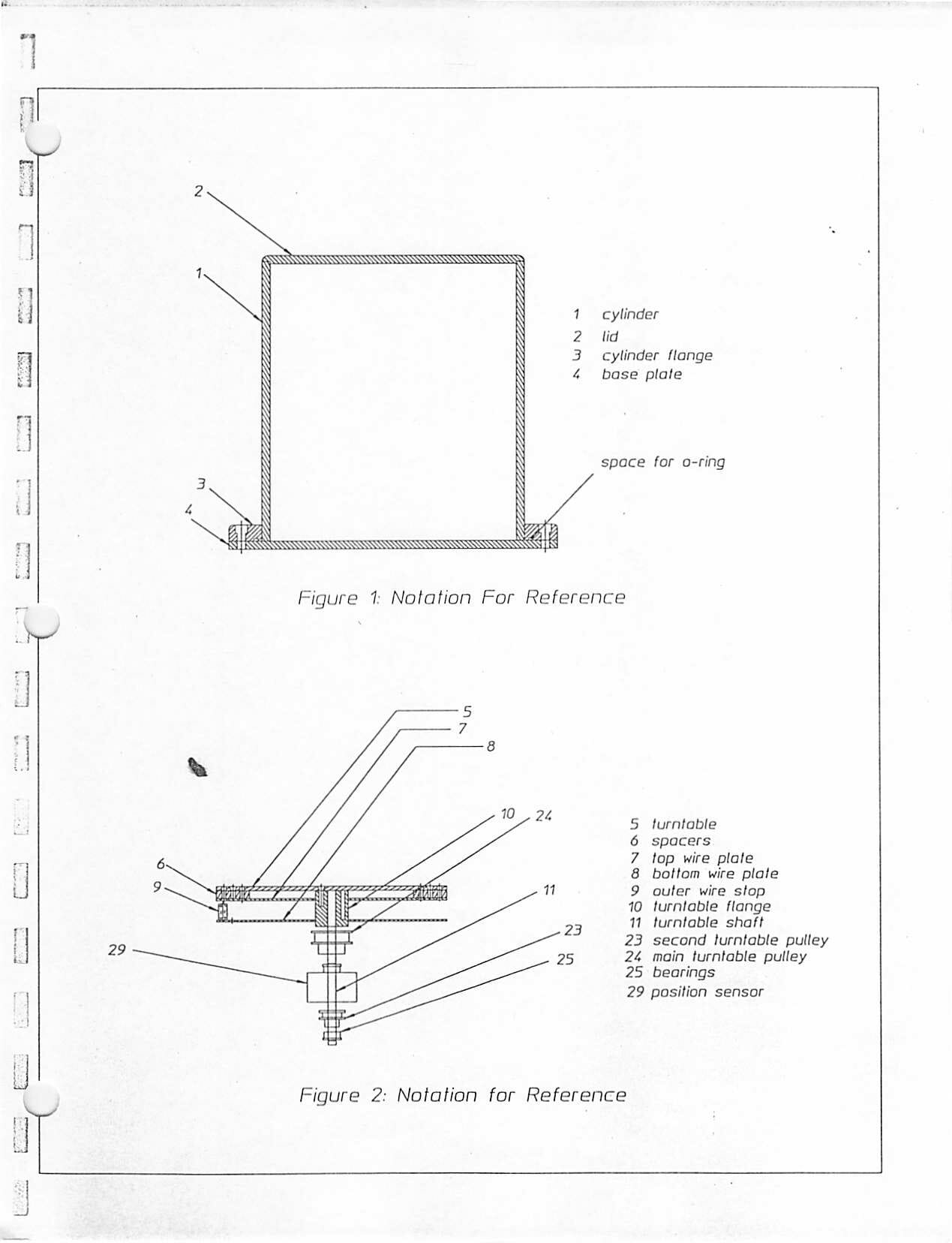
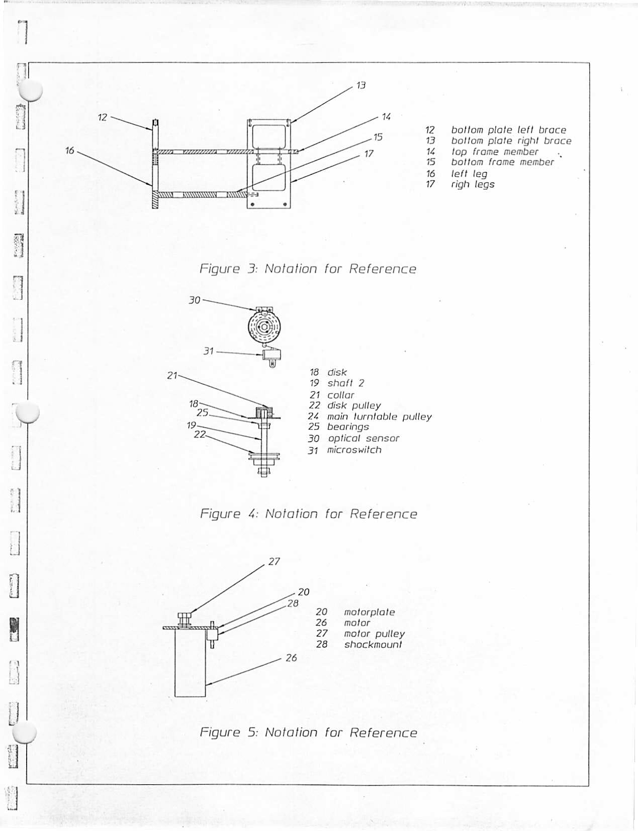
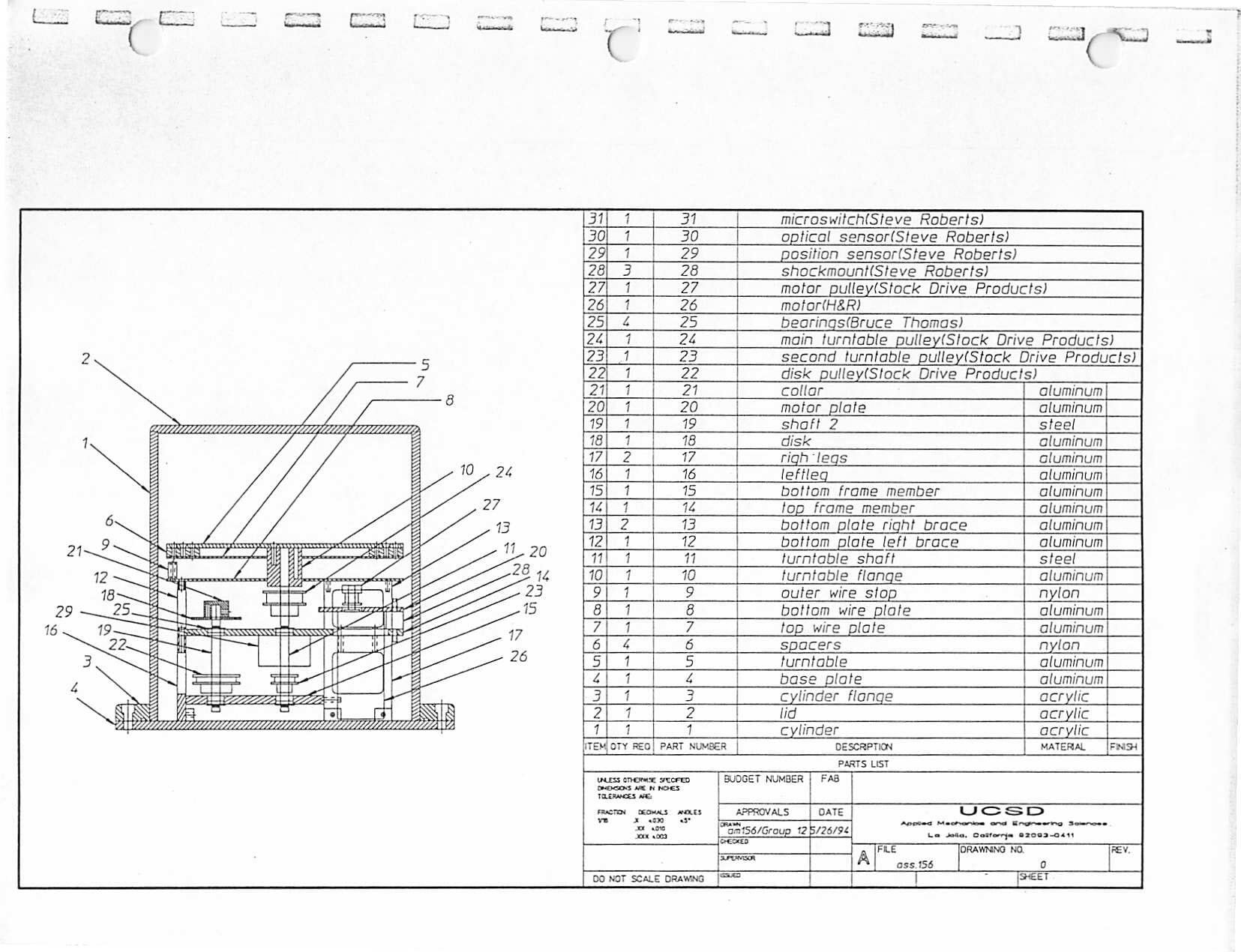
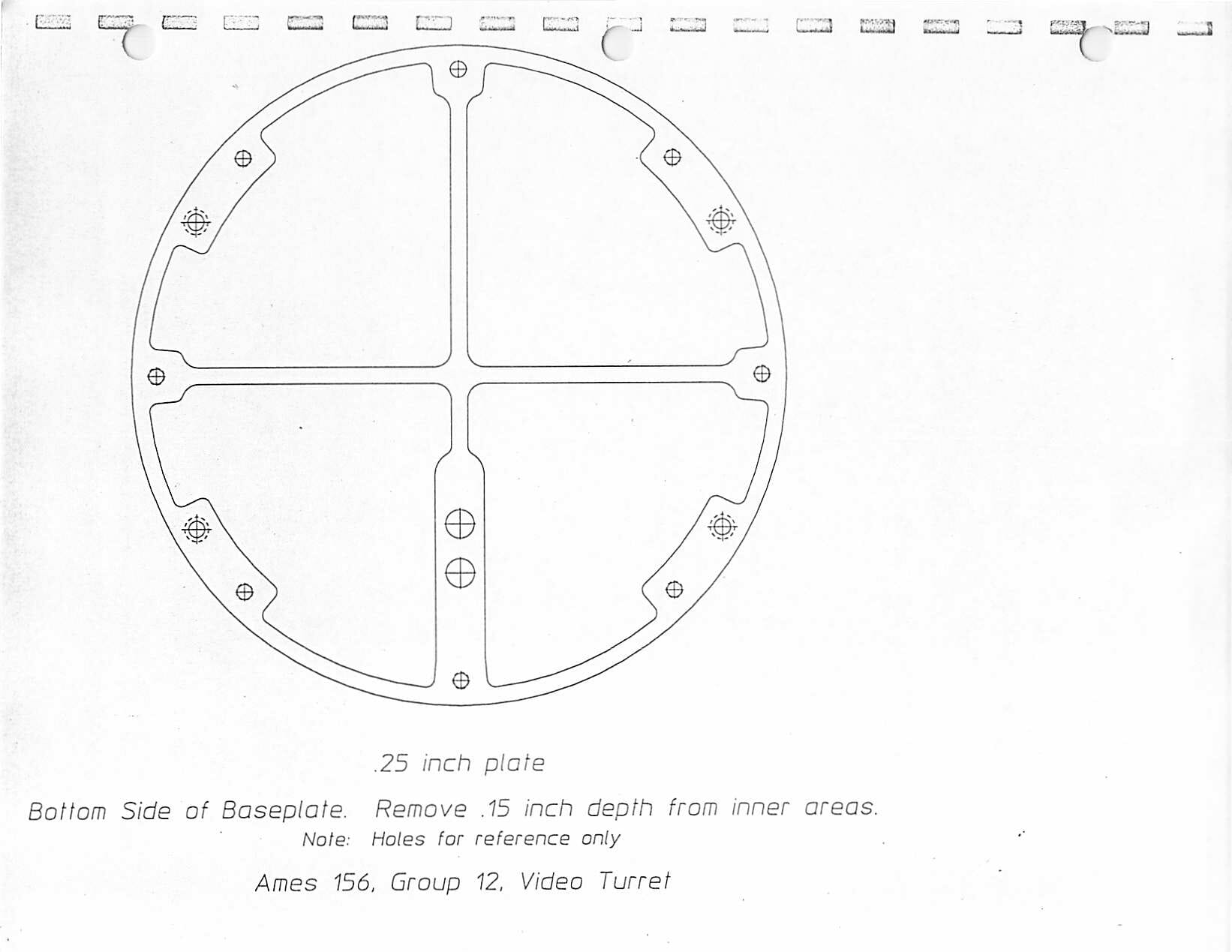
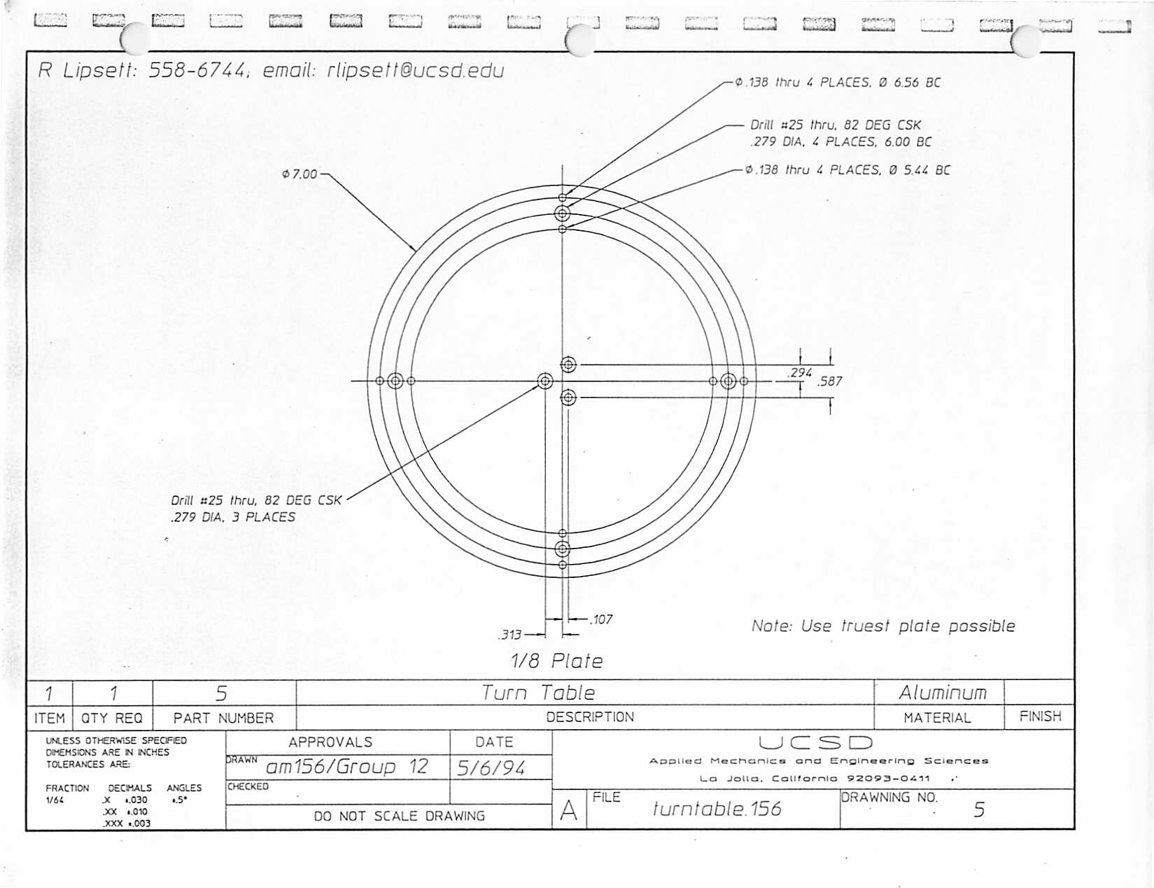
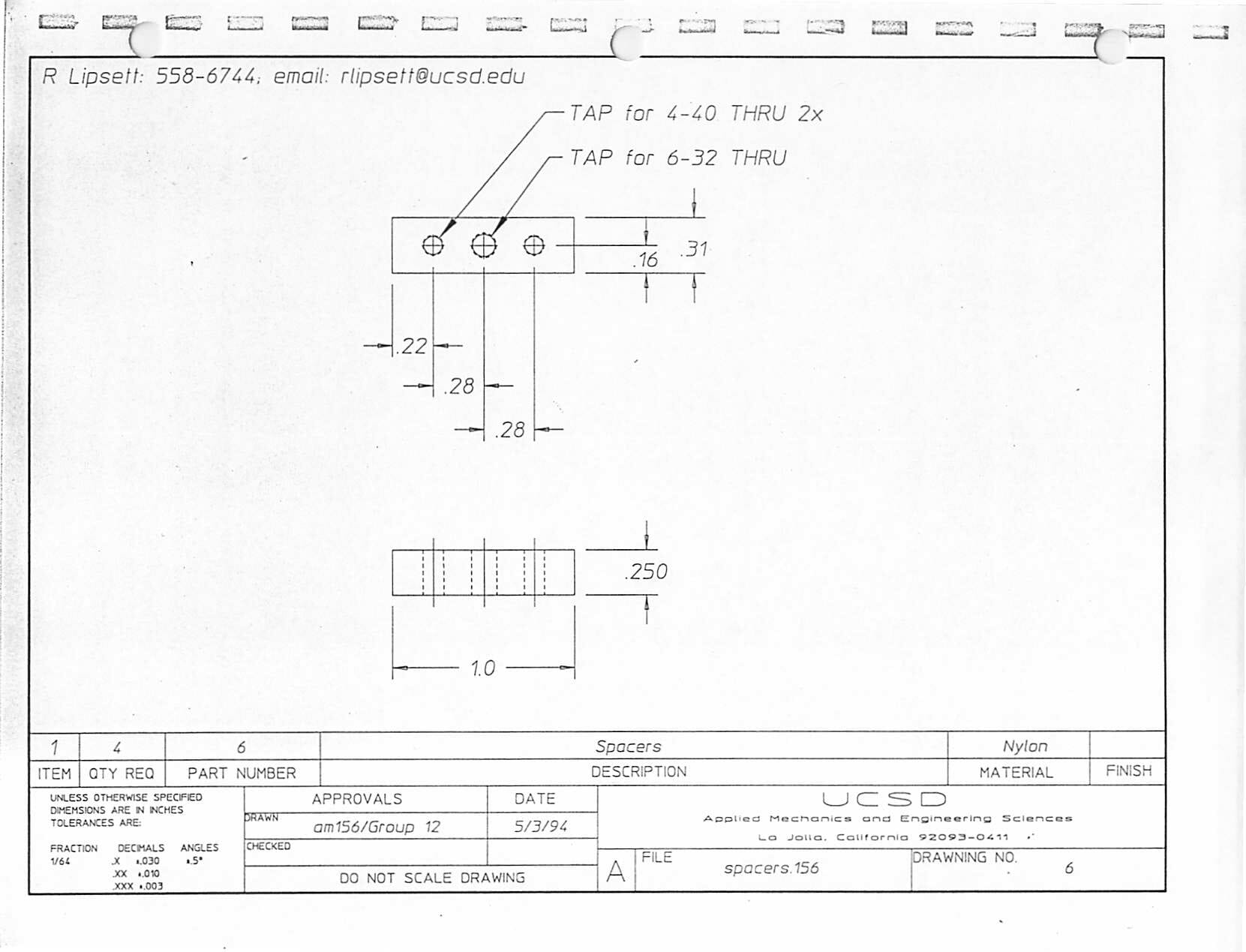
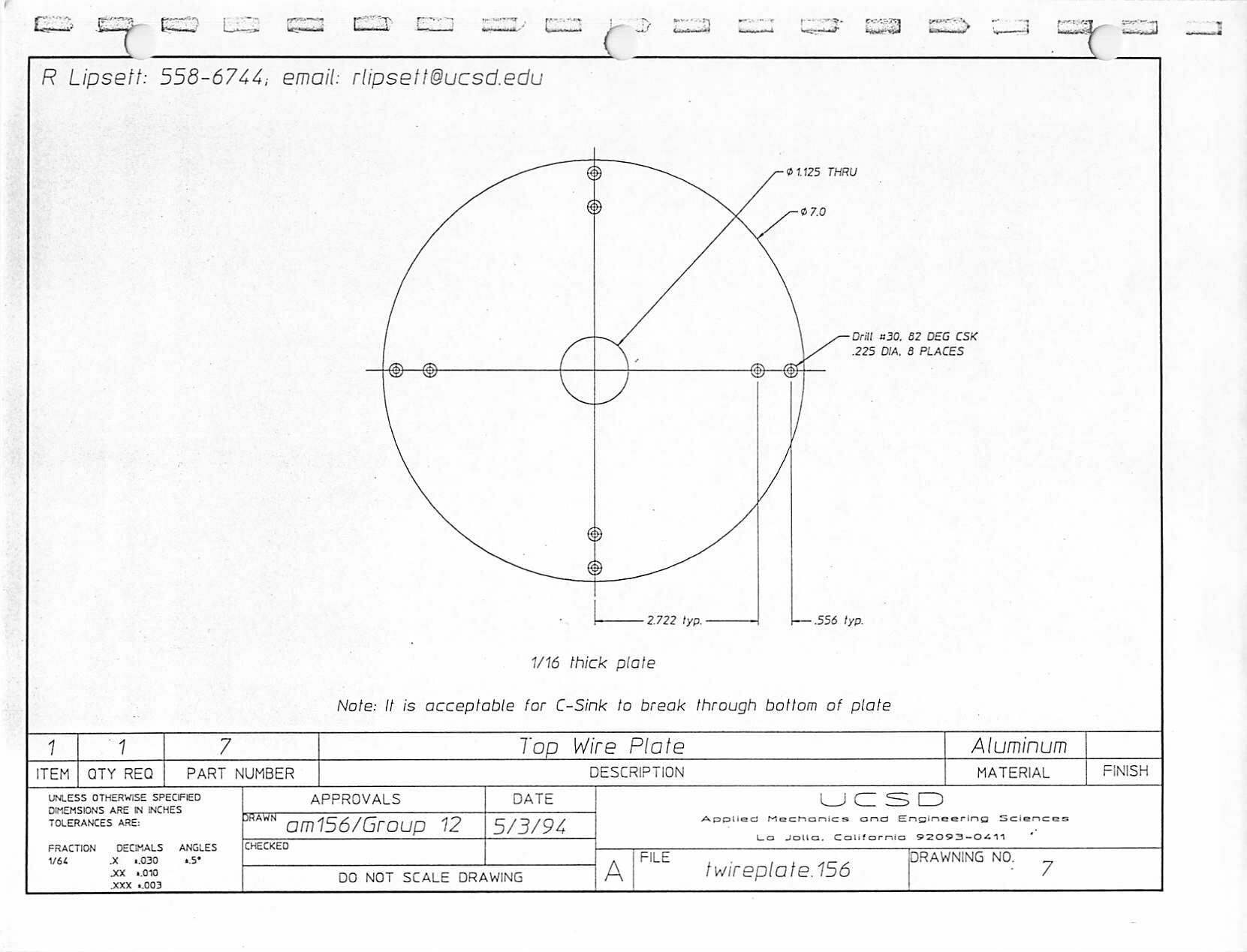
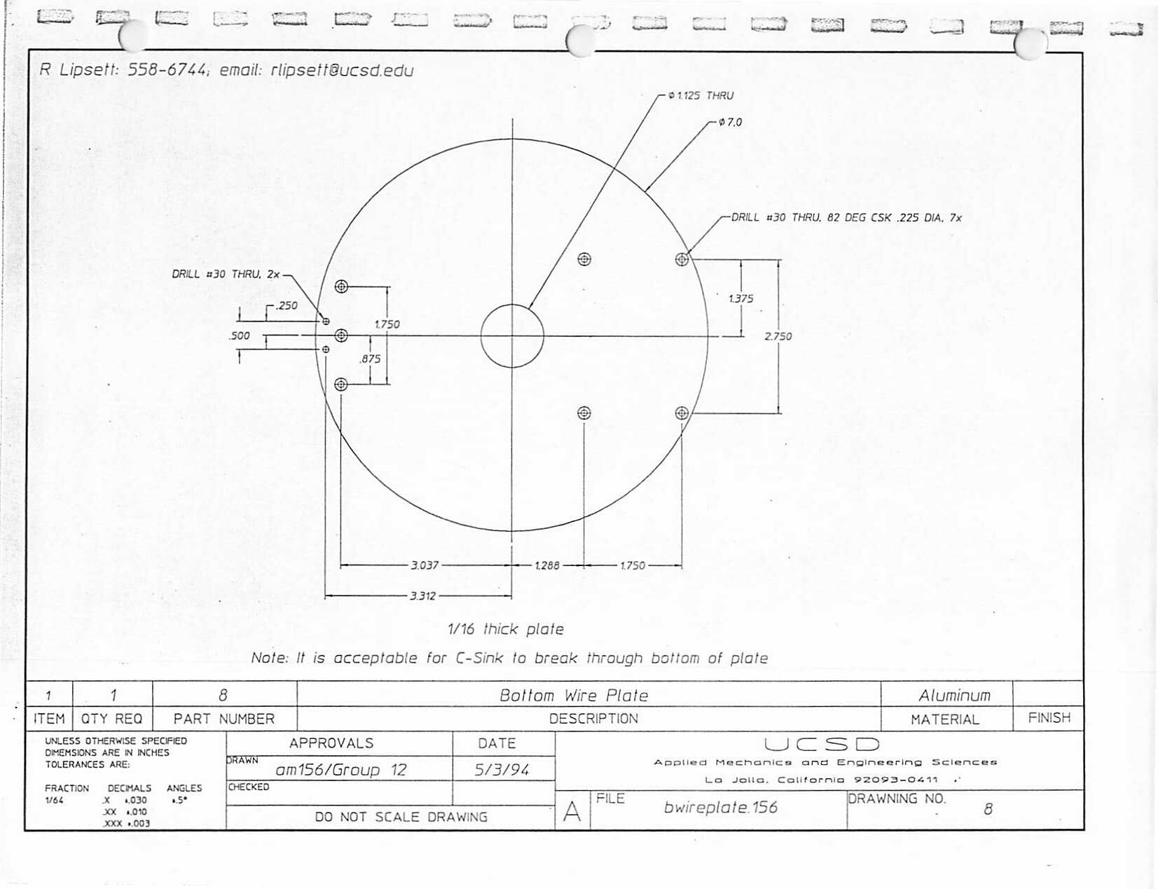
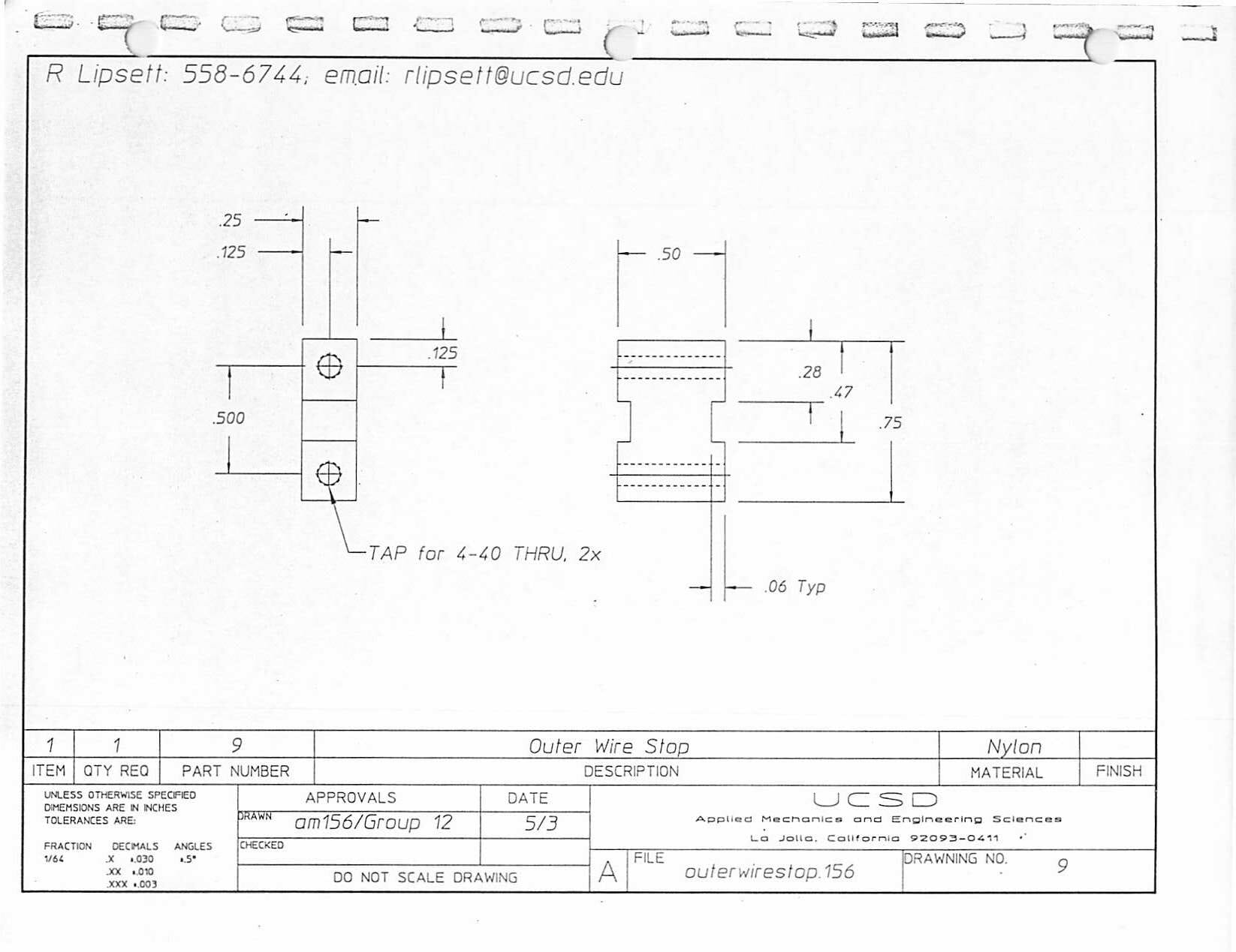
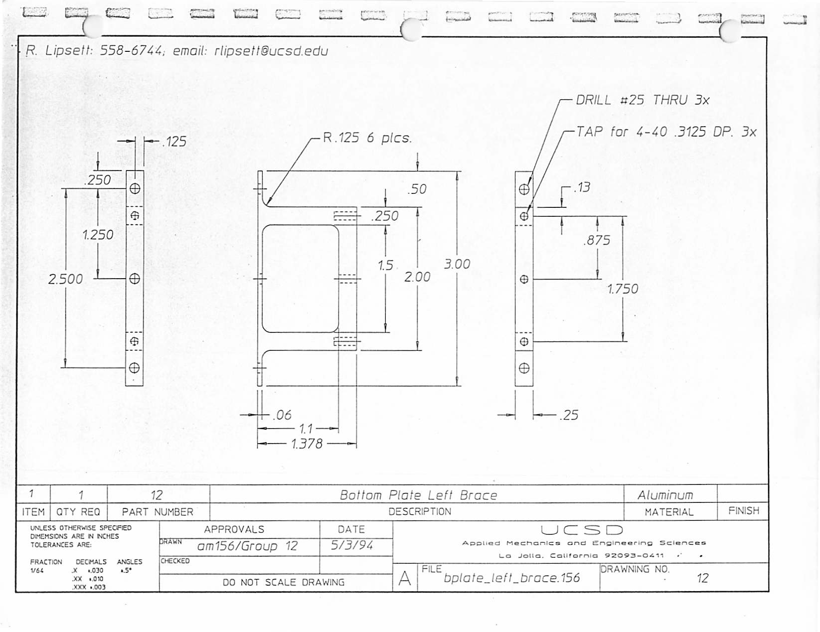
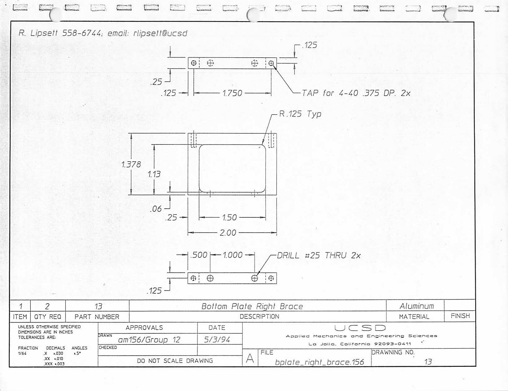
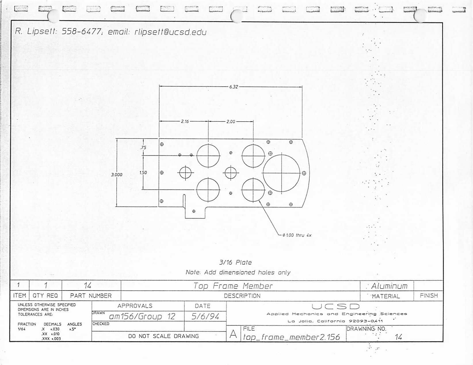
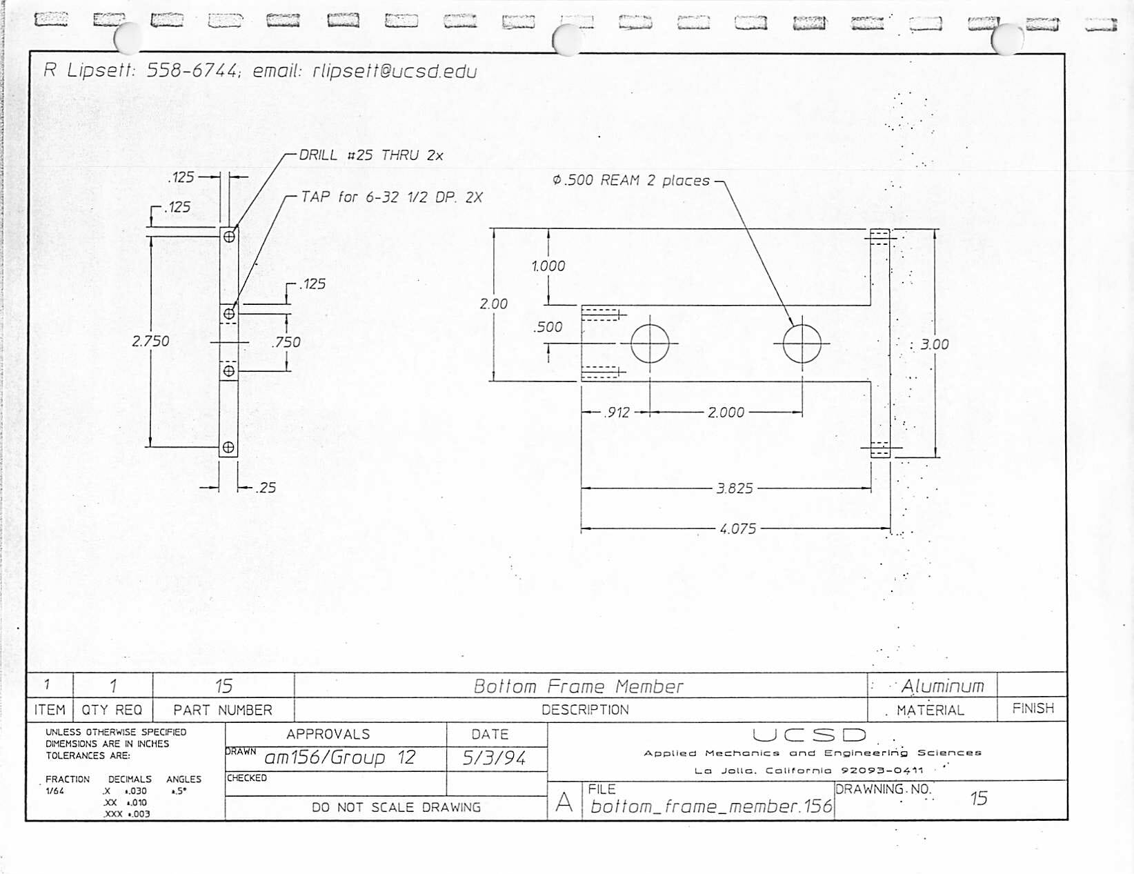
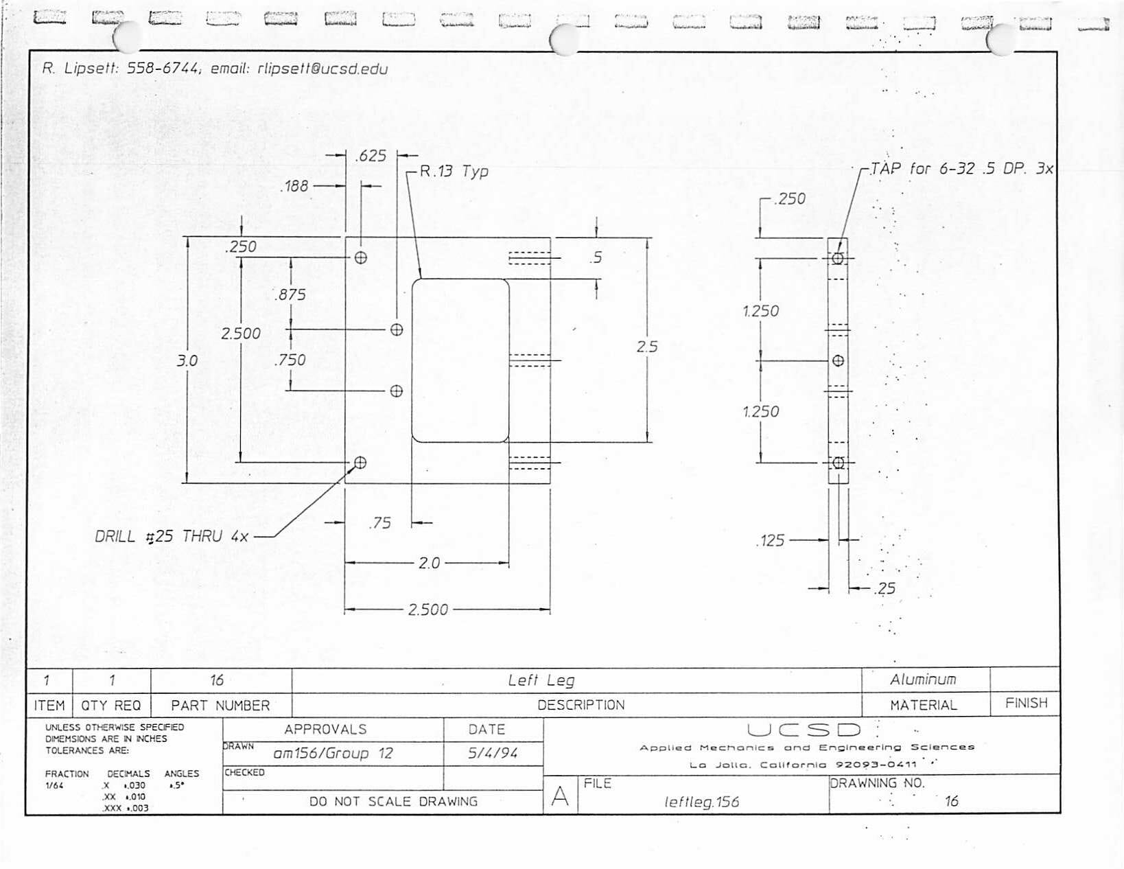
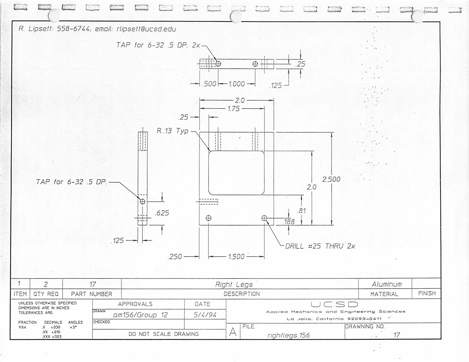
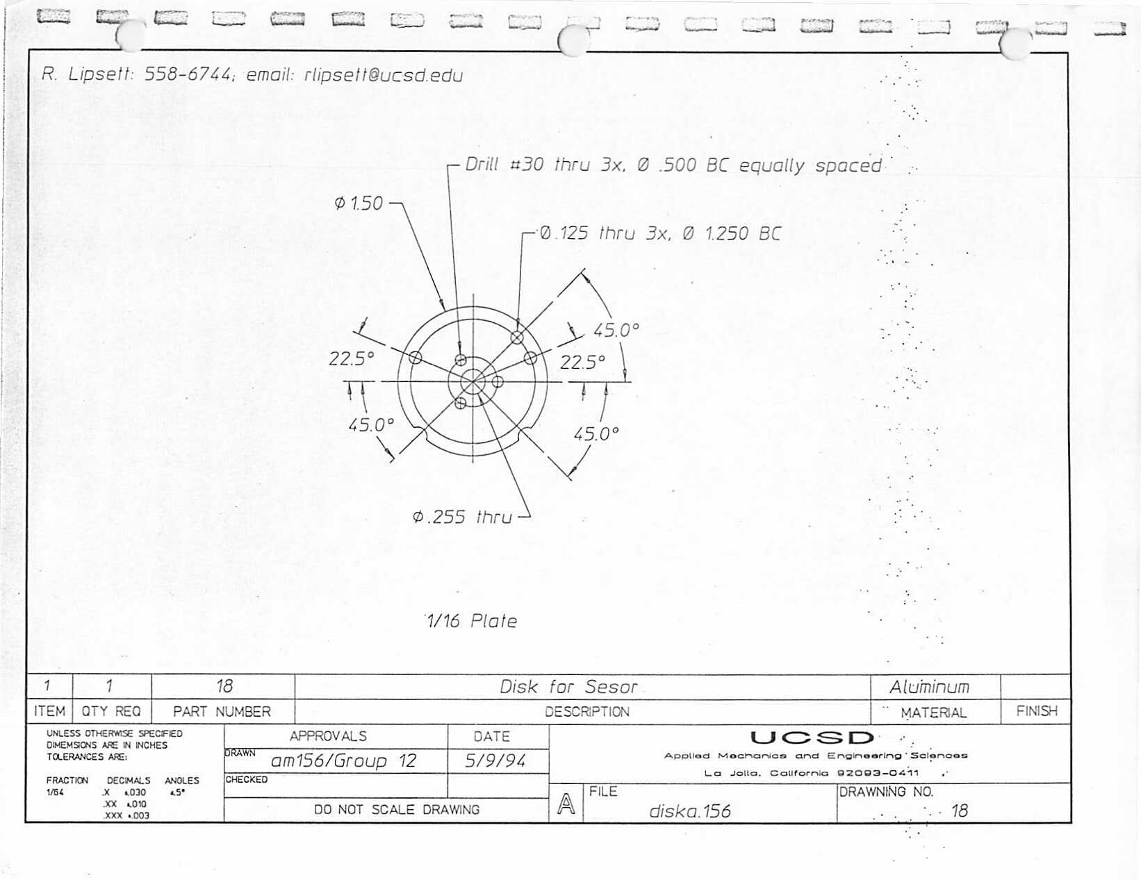
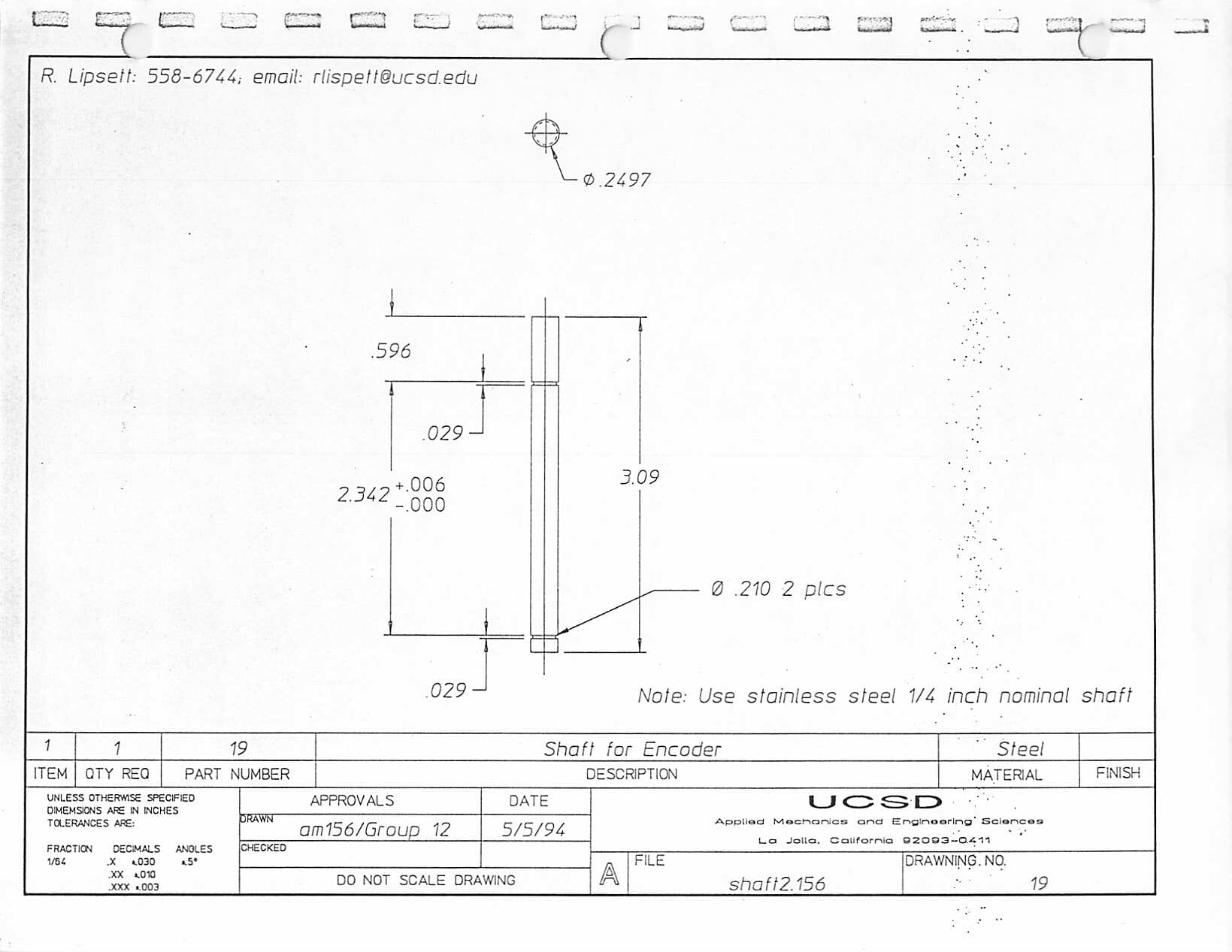
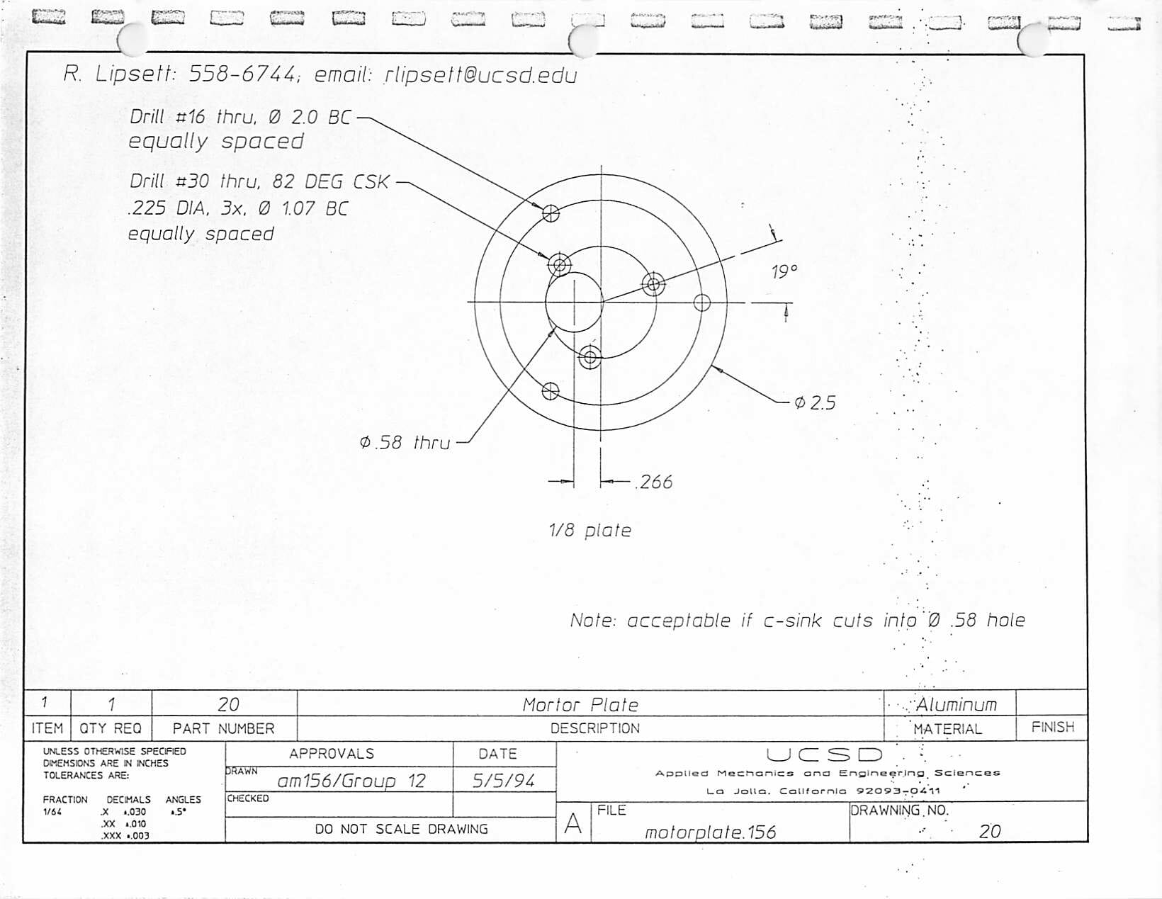
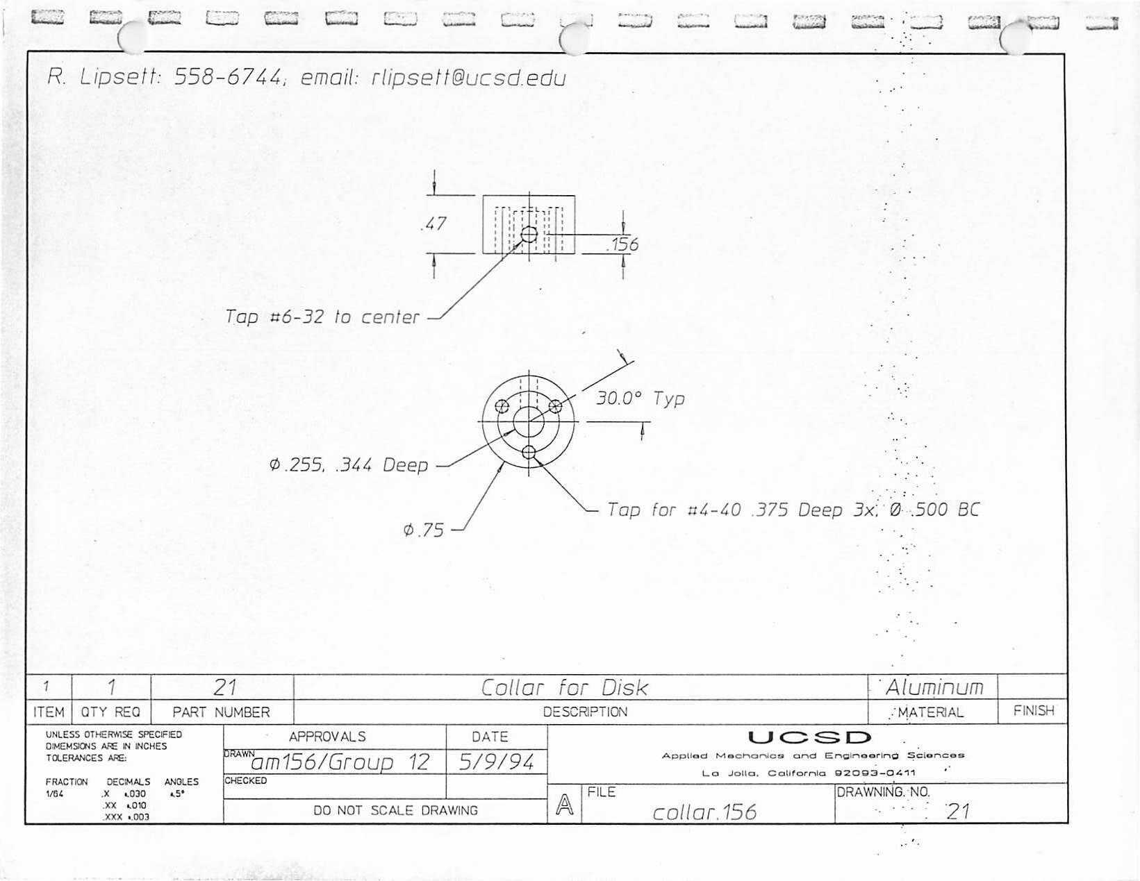
Mechanical Drawings
These were all created by Robert Lipsett, the Mechanical Engineering student at UCSD who designed the physical internals of the video turret. All can be clicked for larger versions.