These tattered drawings recently turned up in the lab… and it occurs to me that I have never done a proper article about the rather too-elaborate engineering of the hydraulic systems on the Microship for rudder and landing-gear control. Here is a quick overview of this essential subsystem.
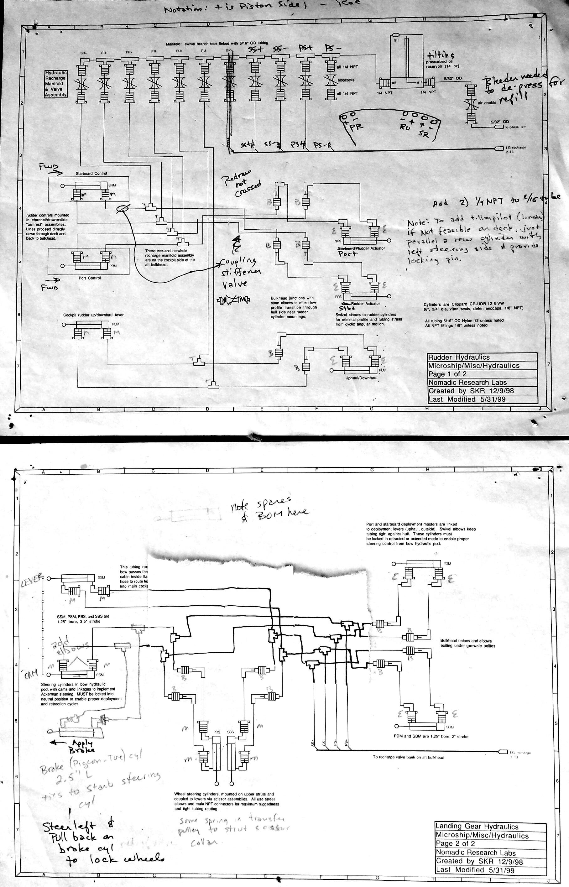
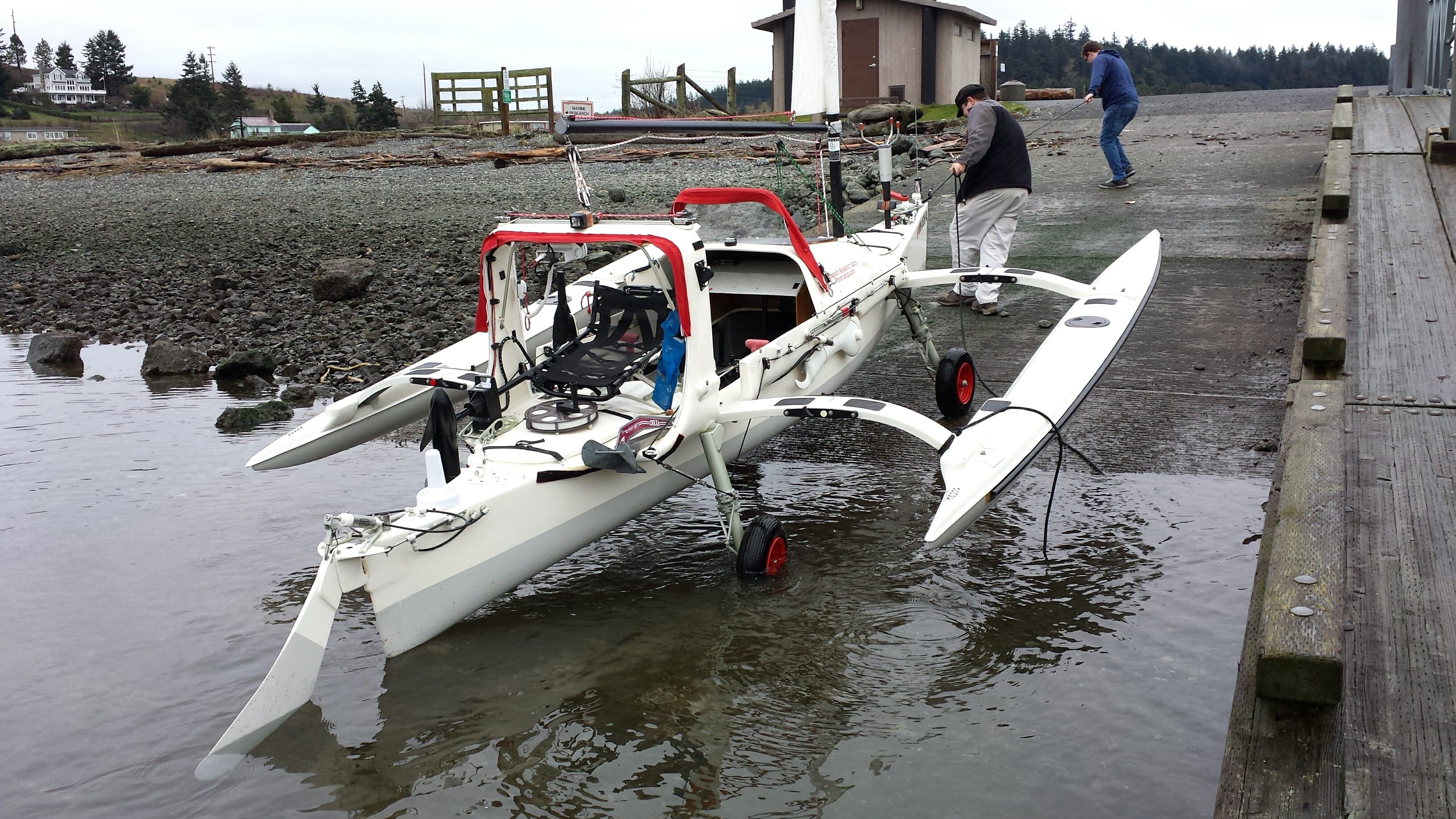
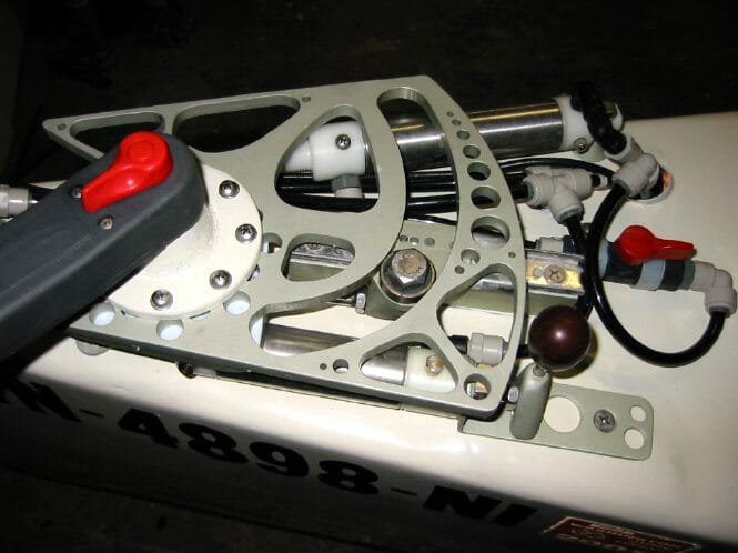
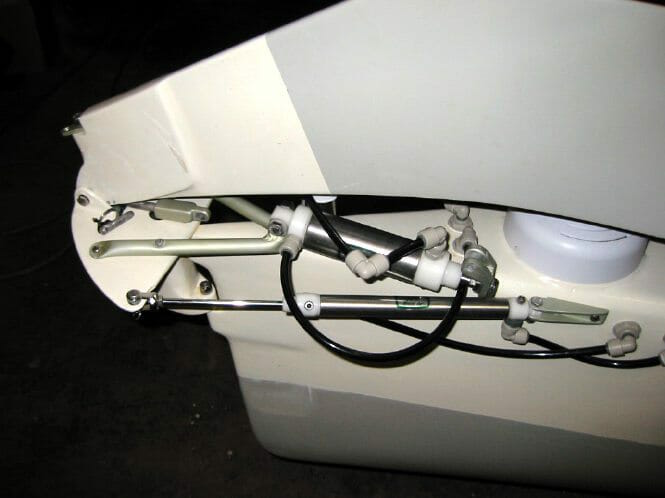
The boat’s hydraulic system is made up of 13 cylinders as well as a calibration manifold. First, here is a dockside photo showing landing gear retracted, and the steering controller on the bow:


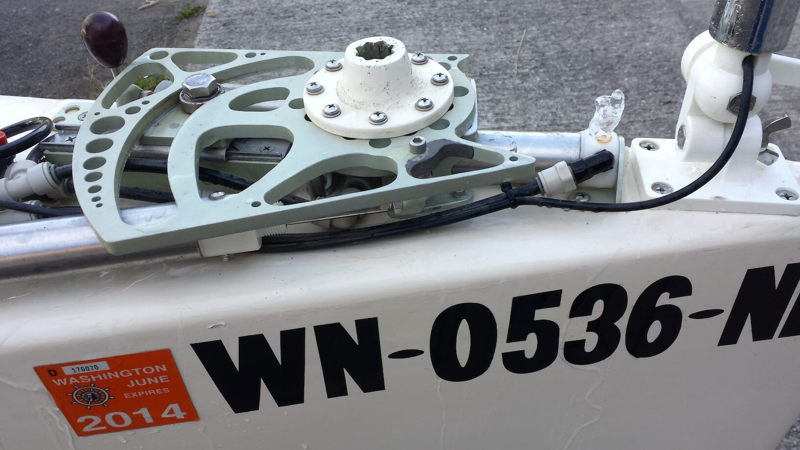
This has two inputs. One is from the steering assembly on the bow, which uses a winch handle plugged into that molded socket to rotate the cam plate. One cylinder has a follower that tracks the curved slot, and another is actuated by a pin at a calculated distance from the rotation axis. The combination implements the Ackerman steering function, where the inside wheel turns more sharply than the outside wheel on a turn (minimizing scrubbing and the resulting stresses). A third cylinder is controlled by a simple slider with locking pin, biasing one side to pigeon-toe the front wheels and keep the boat from rolling down a hill (we never could come up with decent brakes). This is especially useful on launch ramps.
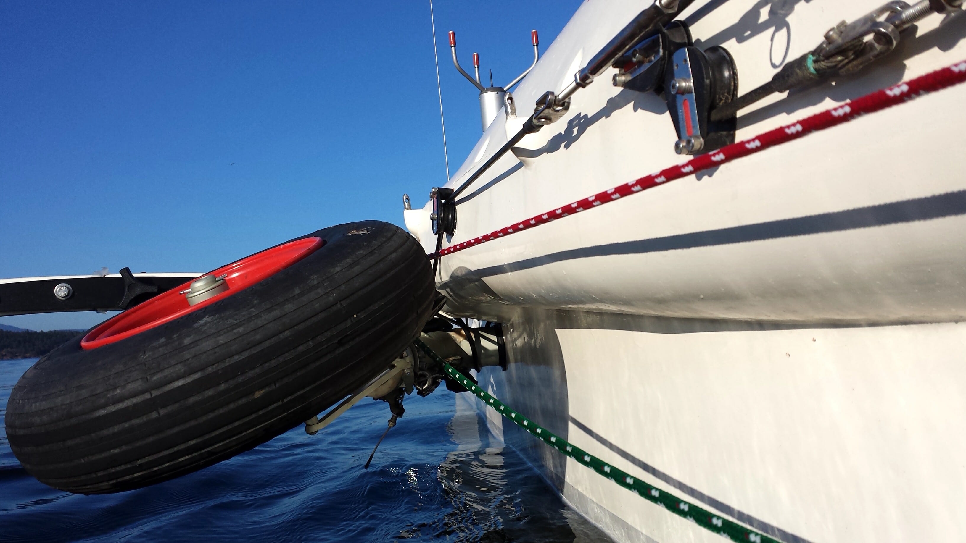
A secondary pair of controls (simply tee’d into the circuit described above) is on two of the four landing gear deployment levers. When the wheels are retracted on launch, they make an approximate 70° rotation as they tuck up under the solar panels… necessary to clear the water. The aft ones are easier, with fewer moving parts: simple bungees pull them into the proper position when they are no longer being held down by the deployment cables. You can see one of these above the Spinfin pedal-drive unit; the perforated arm is one of the levers controlling landing gear position:
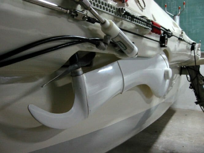
With the gear up, the wheels clear well underway and don’t drag in the water:
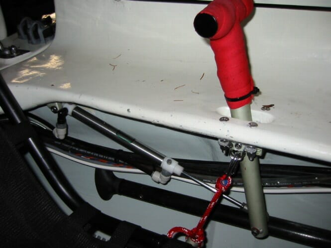
The rudder system has two parts… steering and retraction. The T-handles mentioned above make for a very comfortable control system, and simply pivot through a fixture in the “decklets” to a hinged cylinder:
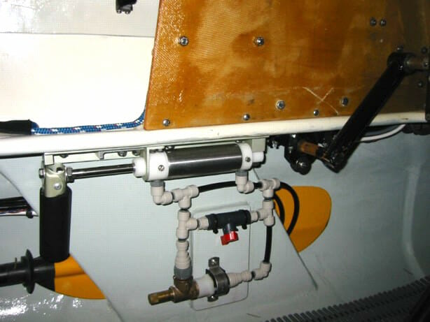
The other input to the rudder is responsible for deployment as well as automatic kick-up in the event of grounding; this is done with a pressure-release valve. This is all located on the daggerboard trunk for easy access:
At the rudder end, this all comes together with a pivoting headstock assembly that carries a precise vertical slot and retraction hinge point. It is shown here retracted; underway it is vertical, supported by those cheeks:
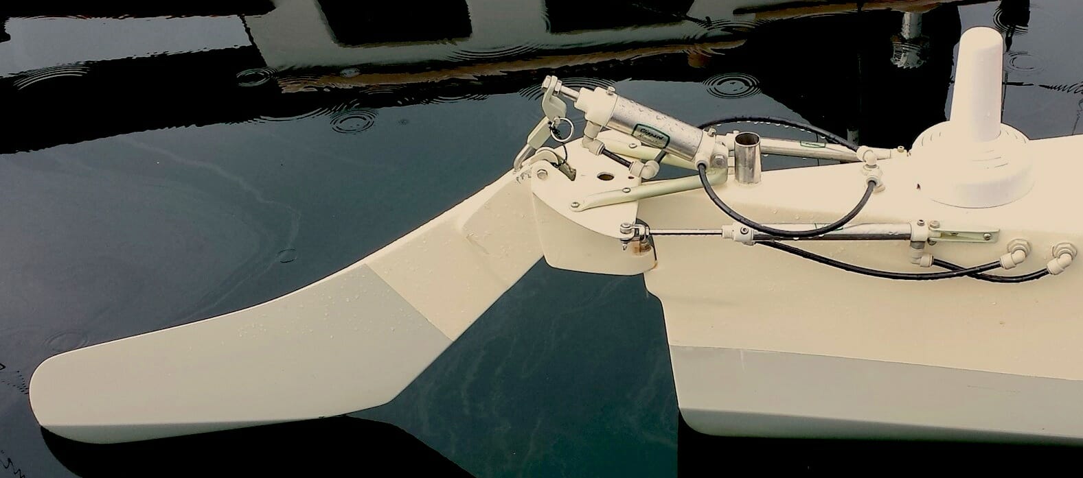
The retraction cylinder can only take it to the level shown above; on the road, the ball-detent pin just above the hinge point is pulled and the rudder is flipped over the deck for protection:
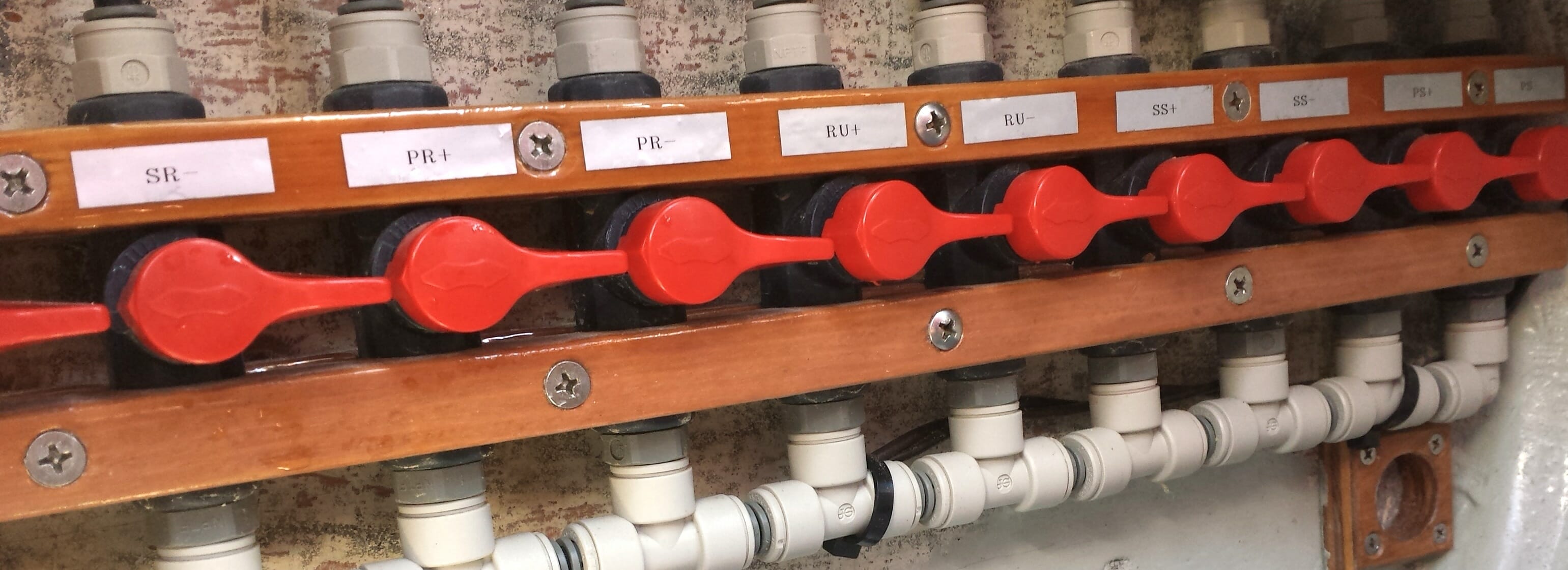
Here is the calibration manifold behind the seat. Each of these stopcocks, when opened, shorts one leg of a circuit to a “bus” that is connected to the reservoir. If two are opened corresponding to a single cylinder, then it can move freely… making it very easy to tweak the positional relationship between input and output. This was commonly done to center the T-handles that control the rudder (with separate circuits for both sides, giving tighter control along with a backup if one were to fail). Also, I had a slow leak in the retraction system, and these valves allowed me to quickly re-calibrate.
The fluid I use is simply… fresh water. Originally, after lots of research, I mixed a fluid that was half propylene glycol and half distilled water, wanting something that would not freeze or support biology but would also not be a mess if spilled. Lubricity is not a huge issue, but compatibility with the various materials was (Buna-N rubber, Delrin, stainless, tubing, and the various fittings). In practice, this was a pain, requiring elevating a tank to get some gravity pressure behind the bleeding process, and pragmatism won. Now there is a simple hose fitting, and I just connect to a nearby bib, open the NPT bleeder ports one at a time, calibrate it, and go sailing. Here you can see one of the bow steering cylinders happily burbling:
Finally, on the road! Here she was in 2013, enroute from my lab to the launch (with my friend Paul Elliott, who helped with the haul):

On the water:

And emerging a few months later, very much in need of a bottom job:

For more information about the Microship, here is an article about her construction. There is also a Microship electronics photo essay similar to this one, with lots of pictures and short descriptions. The tale of her 2103 launch after long stasis is in Microship Revival, and there is a rollicking tale of the Puget Sound mini-expedition 15 years ago.
I’ll close with this shot of the boat being hauled out after a 2015 test sail, when she was considering participation in the Race to Alaska with my friend Nick Wainwright at the helm: