
Building the Microship Trimaran
The ten-year Microship project left a trail of narratives from which it is difficult to extract a clear picture of what, exactly, lies at the heart of this machine. I wrote this to provide that, leaving out electronics, landing gear, hydraulics, pedal drive, thruster, solar array, sail rig, and other complications. This is the story of building a 19-foot micro-trimaran to be the substrate of a technomadic adventure platform… which is now looking for a new home.
The Microship Substrate
by Steven K. Roberts
Nomadic Research Labs
One of the driving requirements of any project is the need to minimize the nightmare of fabrication (unless that process is amusing for its own sake, which is certainly a valid approach). But basically, I believe that life is too short to re-invent the hull, and frankly, if I could have found an off-the-shelf boat that met my needs I would have engaged in epic schmoozing or similar aberrant behavior to acquire a pair of ‘em. We actually tried this twice (with the Fulmar and Hogfish), but the lack of clear project specifications doomed both to failure. There’s a lesson in there somewhere.
OK, if we can’t just go get a Microship, how do we get close? Real™Designers think nothing of conjuring a set of lines, scantlings, and fiberglass layup schedules to address a client’s needs, although these tend to be people who make a career of marine architecture and are not intimidated by the process. But building molds for hulls and designing internal rib structures just to get something that floats, before even starting on the “interesting” parts? Naaah. Not at Nomadic Research Labs—that sounds too much like work. As such, the first few weeks of this project (once we arrived at a clear design goal, which took five years) involved the quest for existing hulls and anything else that would let us avoid Big Nasty Goo Jobs.
Fortunately, people have been making highly efficient, slender boats of suitable scale for a long time… they’re called canoes.
The Center Hull
The objective here was easily stated. I wanted maximum volume in a smooth, hackable hull, tough enough to withstand occasional abrasion and long enough to provide a center cockpit area with room to lay my lanky 6’4” body down to sleep.
The hackability requirement called for a hull material that would accept epoxy and thus allow added fiberglass structures, ruling out canoes made of plastic, aluminum, or any of a variety of vinyl/ABS/foam-sandwich materials designed to take river-running abuse and provide absolute flotation in case of flooding. A search of available products in the 18-20 foot range turned up a number of vendors large and small, and for reasons of specifications and aesthetics I found myself gravitating to Wenonah. Before long, two of their excellent “Odyssey” expedition canoes were enroute to the West Coast from the company’s plant in Wisconsin.
The boats were slightly customized by the manufacturer to accommodate our unusual needs: we had no use for the usual canoe seats, thwarts, or gunwales, but Wenonah bonded in a pair of 1/2” marine-plywood bulkheads eight feet apart—coinciding with the distance between the crossbeams of a stock Fulmar 19-foot trimaran. Why was this dimension relevant? In parallel with the canoe quest, we had discovered to our delight that we would be able to purchase outer hulls and crossbeams from Fulmar Canada, shortly before their discontinuation of the product. Not only did this save another huge load of work, but it freed us from having to come up with this dimension ourselves through some arcane combination of marine architecture and rectumology. There would be quite enough inspired guesswork over the next few months anyway, and it’s nice to reduce the number of variables up front.
Stock Wenonah Odyssey Canoe Specifications
- Weight: 42 pounds, with Kevlar ultralight construction
- Length: 18.5′
- Rocker: 0” (this means the bottom is flat from bow to stern)
- Depth (bow): 20.5″
- Depth (center): 13.5”
- Depth (stern): 16”
- Max Width: 35”
- Waterline Width: 32.5”
- Gunwale Width: 34”
The Odyssey hulls gave us an ideal starting point for the project: a lot of interior space in a smooth, lightweight package. In principle, all we had to do to turn them into trimarans was attach the Fulmar parts, a task that for a few exhilarating days was little more than a single line-item on the To-Do list.
The obvious problem is the physical interface with the crossbeams and outer hulls, but we also had to make some early decisions about the design waterline (the line that designers optimistically draw on a boat to demarcate topsides paint from bottom paint), freeboard (how far above said waterline the gunwales are, affecting everything from windage to the dryness of the ride), centers of gravity and buoyancy (ensuring that the boat tends to float in such a way that the waterline turns out to be correct), dihedral (how high the outer hulls should be relative to the center hull to strike a balance between dragging heavily in the water and tipping annoyingly from side to side when at rest), and balance (the overall relationship between stuff that gets blown around by the wind and stuff that hangs under the boat, ultimately manifesting itself in the feel of the helm and general sailing performance). In other words, having a pair of canoes in the lab, perched inscrutably on workstands, failed to reveal an immediate and obvious next step. But at least we had a lot to think about.

Inevitably, much of the noodling that goes on in the early stages of a design is a bit painful to relate. If you recall the spirit of the engineering process discussed in my Gonzo Engineering piece, you know that it takes the form of tossing all the variables into the air, juggling them frantically while studying their interactions and bothering experts with dumb questions, then confidently congealing them into a clear mental model that has to be correct—or appears so until the one expert you were unable to reach finally returns your call and says, “What? No, no, you can’t do it that way; jeez, who on earth told you that?”
OK, maybe I’m exaggerating a little, but I bet if you drag a system architect out to a pub and start the beer flowing, you will eventually extract the admission that any new design involves a healthy measure of unquantifiable art and wishful thinking, stitched together by formal tools and guided by the intuition gained through a lifetime of design work (all adding up to unshakable opinions about what’s right). That’s pretty much what happened here, and in the early phases I depended heavily on others for many of the marine architecture essentials while my job became one of research, synthesis, and conflict resolution; essential wizardry at this stage came from the formidable talent pool of Bob Stuart, John Marples, David Berkstresser, Gino Morrelli, Greg Jacobs, Mark Reynolds, Jim Antrim, Andrew Letton, and a few others.
With such cognoscenti contributing ideas, how could we possibly go wrong?
Gunwales and Bellies
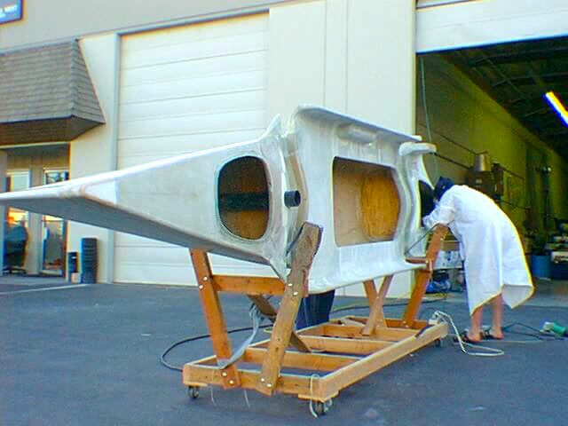
It was obvious from the beginning that the center hull would need more freeboard than was provided by the stock canoe, so we decided to make the boat 2” taller all the way around. This adds internal volume and makes for a drier ride; it has nothing to do with the waterline or buoyancy.
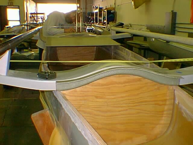
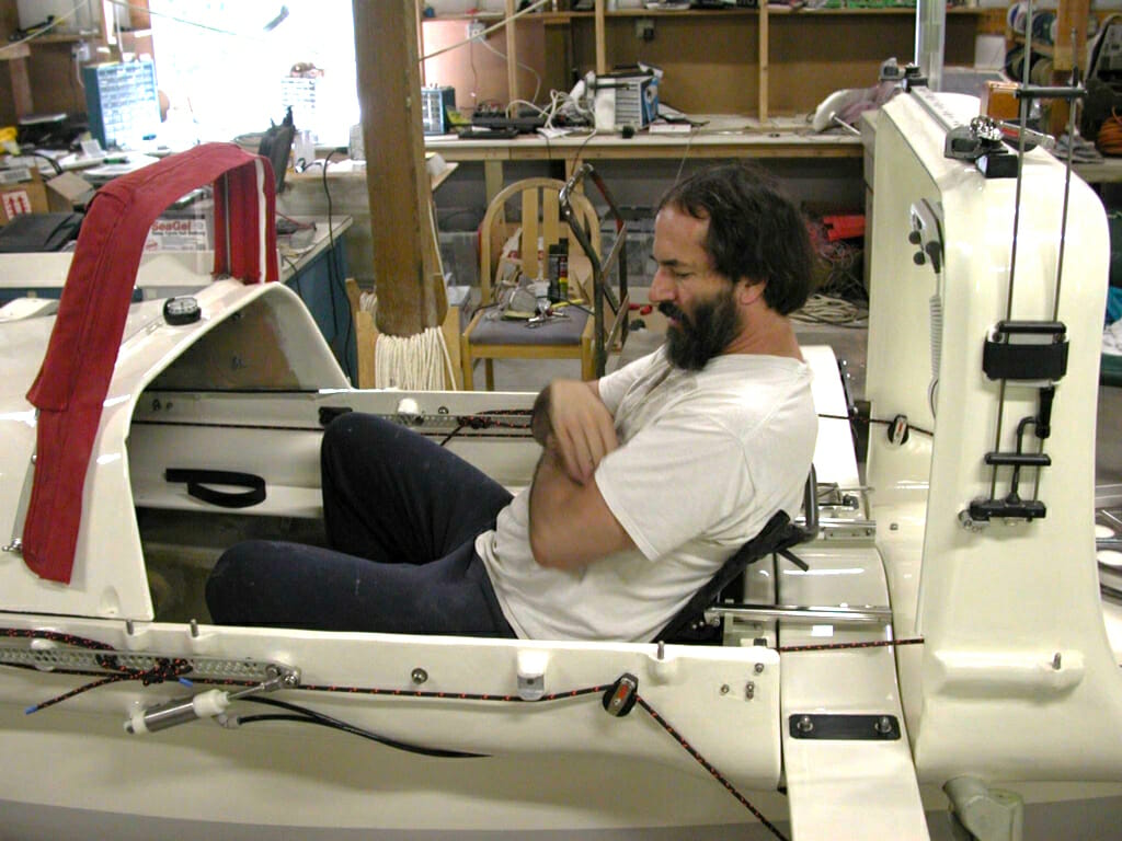
You can see the details of this and some of the other “first steps” in this photo. Up near the bow, Bob Stuart is trying to establish a vertical line for the placement of the mast step (getting a level reference plane is a real pain in a boat, because everything is curved). In the foreground there is a molded aka nest resting atop the aft bulkhead, with one of the crossbeams nestled inside. We’ll discuss this in the next section.
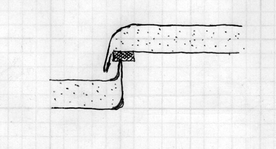
Along the top edge of the boat there is evidence of a bit of surgery in progress, detailed in the drawing below. When the canoe arrived in the lab, the rim of the hull ended with the little square cross-section labeled “original wood gunwale”—less finished than would normally be the case, as we knew we were going to hack it anyway. The single-layer wall below that is a thin layup of Kevlar plus an external gelcoat layer (a tough pigment). Every 2 feet there is a stiffening rib of foam-core material that curves from the gunwale down to join the canoe floor, which similarly consists of two skins separated by a thin layer of foam. The net effect is a nice balance of lightness and rigidity, and we tied into it with all of our subsequent construction.
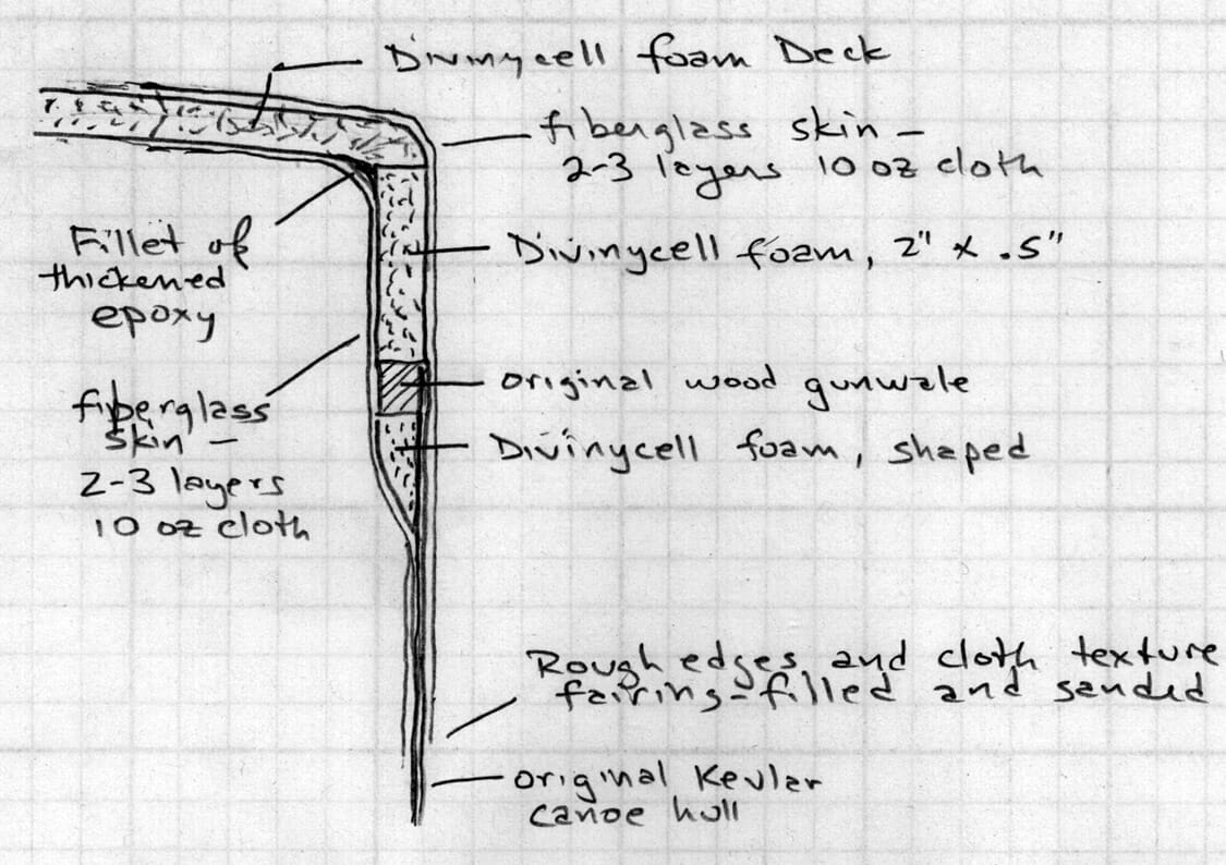
Here we are looking edge-on at our new additions to the gunwales. Below the original wood, we glued in a tapered piece of foam (ripped on a table saw) to allow our added fiberglass cloth to lay smoothly along the hull, as it refuses to bend around sharp corners. Above the wood, there is a 2-inch wide strip of foam, and directly to this is glued the deck, made of identical stuff. Where these two pieces meet (at slightly less than a 90° angle, given the slight crown of the deck for drainage, stiffness, and aesthetics), we sanded the outer corner to a gentle radius and, inside, added a fillet of thickened West System epoxy with the consistency of peanut butter. At this point, all we had to do to make it strong was cut some pieces of fiberglass cloth, lay them on all the surfaces, and squeegee on the epoxy.
The internal view of the resulting structure is shown here, looking forward from inside the front hatch. There are actually a number of details revealed here. Beginning up at the deck (ignoring the hardware and black hydraulic line—that’s part of the landing-gear steering assembly), you can see distinct levels as you move down along the sides of the hull. Starting at the horizontal underside of the deck, there is that 2” tall strip of foam, then the original wood rim, then a different color of foam used for the tapered part. Why different foam? As with most materials in this business, there are lots of options; here, we had less need for compressive strength so we used a lighter material to save a few ounces. The final stratum visible is the overlap of fiberglass cloth onto the original hull material.
Incidentally, those two wooden strips on the sides of the hull are for added stiffness—we were concerned that sailing would subject the boat to much heavier cyclic abuse than originally intended, and these reduce any tendency that the large flat surfaces might have to flex (or “oilcan”) in response to waves. Also, in the foreground of the photo, you can see one of the foam-core stiffening ribs I mentioned above.
At this point, we have a canoe that’s 2” taller than before, and have also established how the deck is integrated with the hull. If we were simply closing an open boat and adding a few compartments for gear storage, we’d be nearly there… but this is a Microship, which obviates simplicity. A simple decked-over hull with access hatches is fine for the bow and stern segments, but the region between the bulkheads is a different story.
Here, we have to accommodate a gadget-happy human with as much space as possible, provide horizontal surfaces in the cockpit for armrests and controls, support the equipment console, install the retractable seat and other essential fixtures, allow room to sleep, and somehow segue into vertical walls that provide inboard support for solar panels. All these needs are addressed by the structure shown schematically in Figure 5-5, which became known as the gunwale belly.

Starting from the bottom, we see the same structure that appeared in the basic bow and stern sections—the pair of foam strips that add 2” of height and let fiberglass cloth lay nicely against the hull. But instead of merging into a simple deck, these now tee into long curved foam sections, running the full eight feet between bulkheads. After considerable experimentation, we discovered that the Divinycell core material will easily take simple curves through a carefully calibrated thermal process involving industrial electric strip heaters and a bending jig of 4” PVC tubing to provide a consistent radius. In retrospect, it would probably have been better to bend longer sections at once than we did, as the minor variations in the process translated into a lot of sanding and filling later, but such is the nature of prototypes.
You can see the results below. Closest to the photographer is the opening for the aft gear hatch, and the gunwale bellies adjacent to that are thicker than the rest—2 inches, to be exact. These are the “roots” of the arch structure to be added later, providing support for a fabric enclosure reminiscent of an automotive convertible top, as well as mounting space for all sorts of essential equipment. The little foam triangles between the arch roots and the hatch opening will provide surfaces for the electric thruster (port) and the anchor (starboard); the different foam color, as before, is because we didn’t need as much compressive strength in this area.

Just forward of all that is the aft aka nest, and as that’s the subject of the next section I won’t say anything about it here. Continuing in the same direction, we come to the cockpit area itself—a huge opening flanked by those segmented gunwale bellies (still raw Divinycell foam, not yet fiberglassed. Now you can start to see what they’re good for: once the seat is installed, these horizontal surfaces, or decklets, end up becoming a significant part of my immediate environment, much easier on the arms than the original thin canoe gunwales. The big rectangular hole on the starboard side will become part of the trunk that houses the pedal drive unit.
Note the horizontal flat section just forward of the open cockpit space. This is the floor of the equipment console area, which will be packed with computers and communications gear. Just below it, you can see the forward bulkhead (where the battery box will go), and the last visible feature before we reach the limits of the cheesy flash on that clunky first-generation 640×480 digital camera is the forward aka nest. If you squint at the picture just right, you can also see a black object that appears to be atop that—that’s the mast step, which we’ll get to shortly.
It’s funny… it all seems to go so quickly when I write about it like this. One might be tempted to conclude that construction proceeded just as smoothly. But in these early stages, we were faced with the problem of accommodating all future needs, some of which had barely been articulated. While certain features were defined by the chosen hulls and crossbeams, we were still vague on a few details; all I can say is that it’s a good thing fiberglass and foam are so editable!
OK, let’s look at those critical hull-crossbeam interface widgets.
The Aka Nests
You’ve seen them already in the photos above. The task here was to take a pair of curvy crossbeams designed for a small commercial trimaran, and somehow graft them onto a canoe. There are no off-the-shelf brackets that do this, and crudely bolting them on without thinking about stress distribution would be asking for premature failure. The solution was to mold custom nests.
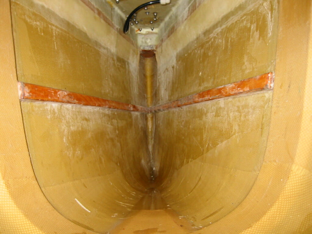
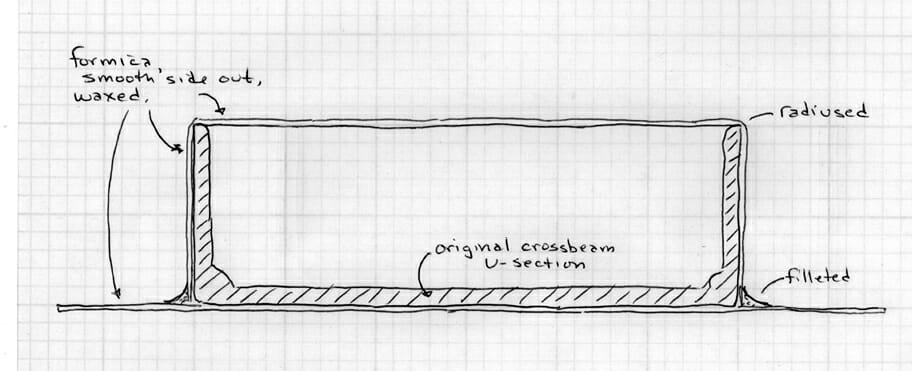
The crossbeams from the Fulmar are U-sections, meaning that they are open at the bottom. To mold a perfectly mating shape, we had to box them in with something flexible, yet stiff and smooth—scrounged Formica countertop laminate from the dumpster of a nearby cabinet shop turned out to be perfect. We simply cut strips on the table saw and hot-glued them to the crossbeams, as shown in the cross-sectional drawing:
For this to work as a fiberglass mold, there are a few requirements. First, since the fabric will absolutely refuse to wrap around square corners, it is necessary to radius the outside corners and fillet the inside ones. We carved the radius with a laminate trimmer (basically an agile little router), and immediately ran into the problem of removing so much of the thin Formica material that our glue joints started to fail. We changed to a tighter radius and got it to work with more aggressive gluing, realized that at least the first few fiberglass layers would have to be on the bias (with the weave at a 45° angle to the edge, allowing it to make a sharper bend). The fillets were easy—filled epoxy applied with a tongue depressor and sanded smooth. Finally, the whole contraption was given a few coats of mold-release wax, ensuring that the new layup would not become a permanent part of the crossbeam… we do need these to be removable!
Adding cloth is time-consuming but straightforward. Each nest was given 6 layers of 10-ounce cloth, yielding a final thickness of about .060”. (Additional strength would be added where needed later, during integration with the boat.) We kept the process flowing, allowing each layer to gel a bit before adding the next, thus ensuring a good chemical bond.
After final cure, we popped the parts off the molds, a process that is always, for some reason, incredibly satisfying. The waxed Formica surface left a very smooth interior finish, and all that remained was cleanup of the ragged edges prior to bonding them to the hull.
Somewhere in here, a rather large question arose: where, exactly, do these things go? Their distance apart was defined by the existing Fulmar aka/ama assembly, of course, but the variables included fore-aft placement of the whole affair, height above waterline, and amount of pitch-axis tilt relative to the center hull. This called for many hours of staring, sketching, and calling experts; we finally concluded that it should go, yes, right about here. As with many such decisions, what looked and felt like a SWAG (scientific wild-ass guess) was actually built upon a lot of research, but this was one of those areas where verbal explanations from marine architects carried more weight than objective measurement of waterplane areas and angles of attack.
The nests were glued in place using the whole aka/ama assembly as a fixturing aid, then gradually accumulated layers of fiberglass that rendered them permanent parts of the boat. The only remaining issue was the attachment method that would allow easy removal of the crossbeams.
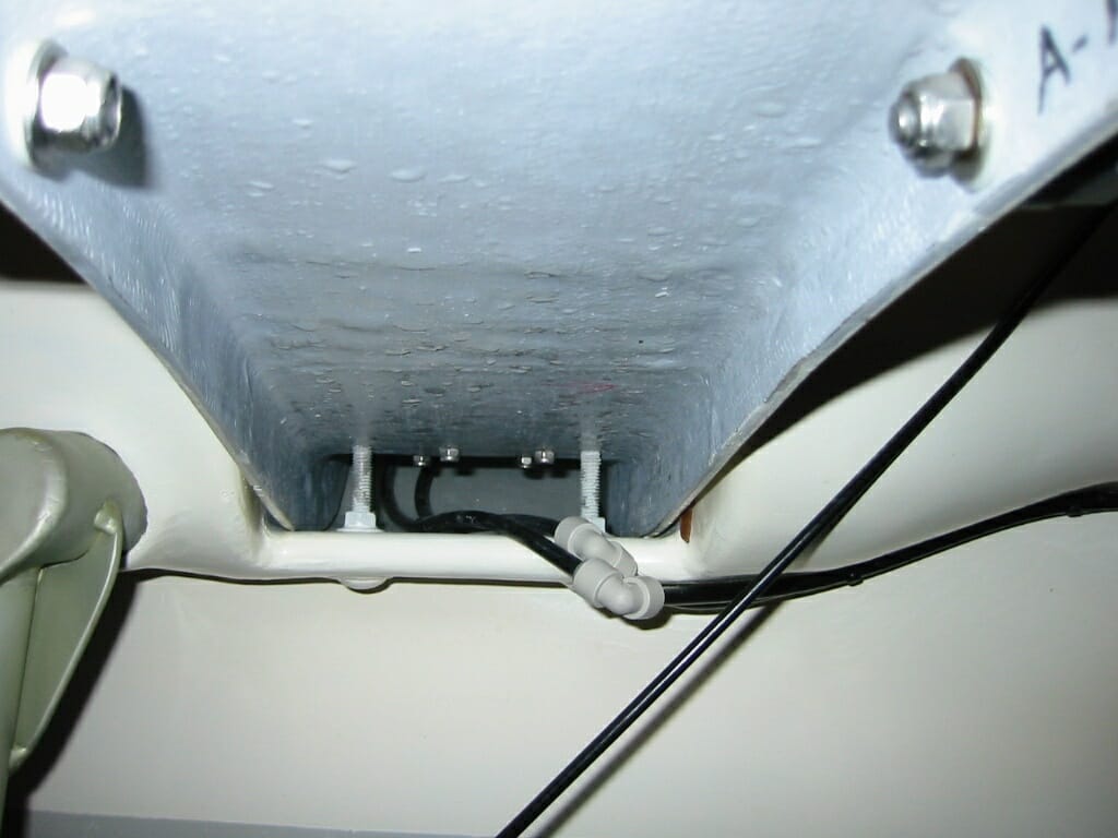
If you think about the “load case analysis,” it’s clear that across most of the nest there is actually very little stress. The real action happens where the crossbeams meet the hull, and almost all of that stress occurs when the boat is fighting heeling forces from the wind in the sail (recall that the wind is often doing its best to push sailboats over, and a trimaran fights this influence through the buoyancy of its outer hulls instead of the mass of a keel). While this is happening on one side, the other is just supporting the weight of the outer hull, insignificant by comparison. In other words, we really need to be able to deal with high intermittent tension loads. This all translates into 3/8” stainless bolts bonded into a relatively incompressible wood-core substrate well-glassed to the surrounding structures, poking through the top of the crossbeam, and captured with acorn nuts along with something to distribute the load and avoid crushing glass fibers.
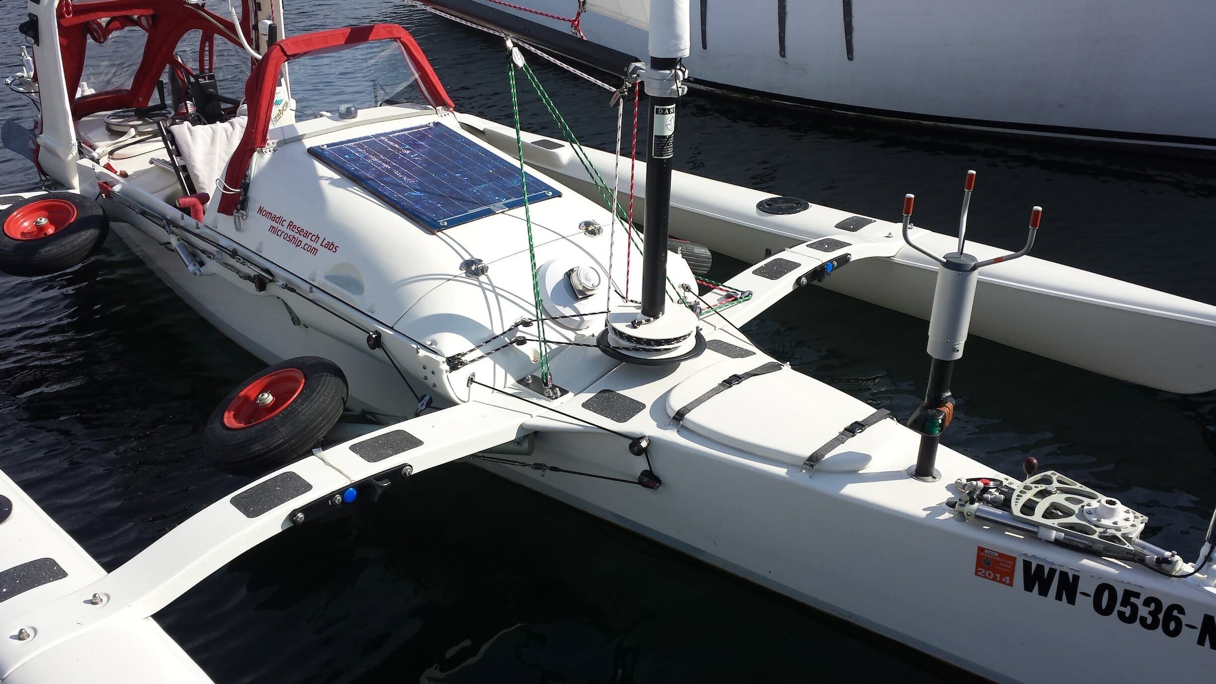
There comes a point in boatbuilding whereon the vessel starts to appear as one lovely thing instead of thousands of bits of foam and glass all glued together in a patchwork of multicolored fillers and epoxies. We’re not there yet in this discussion, of course, but this sneak preview should give us hope, while clearly showing the top view of the aka attachment:
The Arch
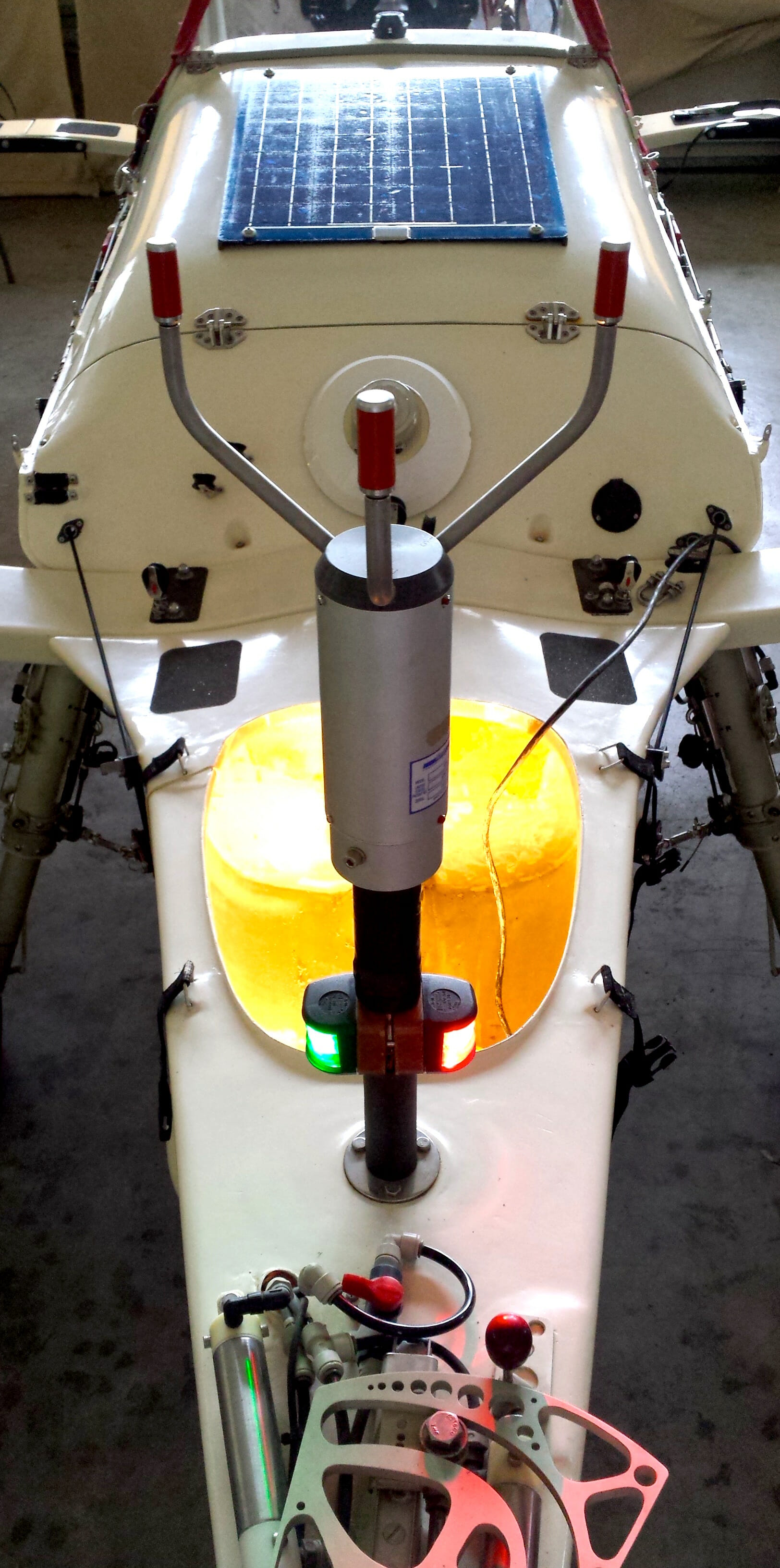
While we have that photo to look at, let’s talk for a moment about the distinctive square structure behind the seat. As Microship design progressed, it became ever more apparent that there would have to be a way to define an enclosed cockpit space more substantially than with a rickety folding frame of metal tubing, as is often used to support the fabric dodger or bimini on small cruising vessels. A decent integrated structure would offer a lot of advantages: mounting space for cockpit fixtures (you can just barely see the face of the Marine VHF radio in the photo), support for an antenna and radar reflector as well as the stern navlight, and—perhaps most significantly—a substrate for a traveler that allows the point at which the boom is sheeted to be moved from side to side, giving more control over sail shape and angle to the wind. That is the horizontal rail-like object atop the arch, and that wonderfully arcane vertical thing in the foreground is a dual-band J-pole antenna for amateur radio.
From a fiberglass perspective, the arch is a direct outgrowth of the deck, though we used a very lightweight blue insulation foam, sculpted it into a pretty shape, and laid on the glass. In retrospect, we probably should have chosen a proper structural foam like lower density Divinycell, for the cheap home-improvement stuff crumbles and cracks at the slightest provocation, making subsequent thread-casting and other retrofit jobs a pain.
Near the bottom of the arch, you can see a little horizontal step with a pin sticking up; that’s part of the solar array mounting system.
Decks and Hatches
During our discussion of gunwales and bellies, we saw how the half-inch foam core was glued at an almost-right angle, then rounded, filleted, and glassed over to make a smooth hull-deck seam. It’s only simple at the forward and aft ends of the boat (about five feet each), but these are very critical areas for mounting surfaces, aesthetics, and the gear hatches. Where else, on this tiny vessel, would I put all my junk?
To achieve a nicely crowned deck, a big flat piece of stock Divinycell foam was constrained in a fixture to induce a simple curve, then glassed on both sides. The tensile strength of the fiberglass is more than enough to retain the shape with just a wee bit of spring-back, so no thermal bending was necessary (unlike the extreme curves of the bellies). Segments of this were then cut out to create the foredeck and afterdeck surfaces, and the hatch covers were made of the pieces left over from carefully cutting the openings that they would cover. There’s a good view of this in this photo, which documents one of those long days of sanding, sanding, endlessly sanding.
We spent a long time pondering the hatches, addressing the basic practicality of providing useful stowage space and the daunting problem of keeping the contents dry… even when green water aggressively hammers the foredeck while I’m out flirting with death instead of spending a storm day safely in camp. I confess that I was tempted by off-the-shelf “opening ports” from the marine supply world, but they are heavy, expensive, and the wrong shape. Most are also designed to be opened from the inside, as apparently, on some boats, there is actually enough room to move around below. Fortunately, I was talked out of this by Bob Stuart, who is less intimated by tricky fiberglass projects than am I.
The hatch covers are deceptively simple. The opening in the deck has a flange that projects upward all the way around the cutout, forming a coaming. To create this, a strip of newspaper was soaked with epoxy, allowed to stiffen but not fully cure, then wrapped around the raw edge of the hole. Once this solidified, it formed a tidy little core for the continuation of both top and bottom layers of fiberglass covering the deck.
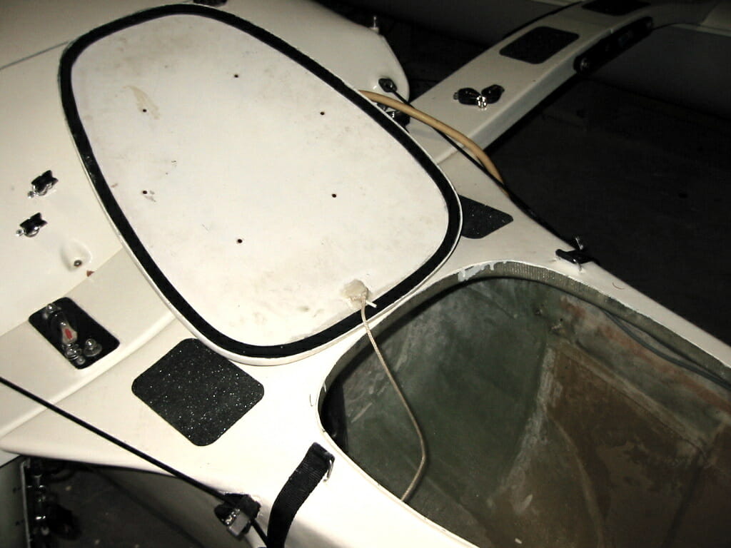
You can see a cross-sectional sketch of this above, and this is the result— showing the flanged hatch cover kevlar-tethered to the boat. These index nicely together, of course, leaving only the problem of waterproofing. That black ring around the hatch cover is a simple glued-on gasket of neoprene (a Silicon Valley dumpster-diving treasure), which makes a good seal when mated with the sharp edge of the deck flange.
Unfortunately, this still doesn’t finish the job. Something has to hold the hatch cover down tightly enough to achieve gasket compression, and this part is a bit sub-optimal. One of the fundamental lessons I’ve learned from early tests of this system is that anything that involves fiddly loose parts is going to be a headache. This approach is pretty; the 1-inch tubular nylon webbing is sewn to stainless-steel D-rings retained in deck fixtures, which were fabricated through a rather tricky process of laying fiberglass “bow ties” over a mold of thin vinyl tubing (later extracted without difficulty, as epoxy doesn’t stick to such things). The result looks sexy, but in practice Out There it involves too many hands—typically, I’m balancing on those rectangular nonskid pads as the boat dances around from the influences of wind, waves, and dynamic body weight. Meanwhile, I’m trying to hold onto the slippery rotating rig, my arms full of whatever I went up there to fetch… then I have to grip the item(s) of interest under my chin while messing with straps that don’t provide enough gasket compression. In other words, if you’re building one of these, trying to extract enough information from the photos and spaces between the lines to answer all the un-addressed how-to questions, please don’t copy this part. Make your hatch covers captive, operable with one hand!
(If I were doing it again or modifying this for an expedition, I would use an internal hidden hinge, a remote-release spring latch, and the existing water-shedding flange system but with more compliant gasket material.)
Mast Step
In many of the photos seen so far, there has been a visible feature that I have hardly mentioned: a black tube poking through the deck just in front of the forward bulkhead. Affectionately known as the mast urbator, this accepts the 21-foot freestanding rig, which is then free to rotate on its Delrin bearings. Since this glassed securely into the hull we should introduce it here.
The primary requirement in this area is brute strength. If you think about what’s happening in a high wind where all the transient and static loads are concentrated, it’s clear that this has to be one of the strongest places on the whole boat—and it’s no coincidence that this, the forward bulkhead, the aka nest, and the landing gear are all bonded securely into a single structure. The mast step is shown here, viewed from inside the forward hatch.
The unit itself began life as a chunk of aluminum tubing with 3” inside diameter and 1/8” wall thickness. Since this was to be in a nasty environment and a partner in a bearing relationship, we wanted it corrosion-proof and slippery. This called for a special form of anodizing that goes beyond the normal conversion coating used to increase corrosion resistance—this process embeds Teflon in the surface, yielding an incredibly low coefficient of friction, the hardness of steel, and excellent abrasion resistance. Typified by the Tufram process from Magnaplate, this is used in industry where lightweight parts are needed to replace those of case-hardened steel, but without giving up the desirable surface characteristics.
Once we had the part on hand, the task was to fixture it into the boat in such a way that the mast would stand perfectly vertical. In an environment of curves and and imperfections, this involves standing back with a funny squinting expression, mumbling over bubble levels and tape measures, and wondering how something that looks so right can measure so wrong (and vice versa).
In the photo above, you can see the massive layup that integrates this unit into the hull. We ground the fancy anodizing off the tubing where it would have to take epoxy, then subjected it to an aluminum-etch process (Alumiprep) to allow a proper chemical bond to the surface. The fiberglass is in layers, each slightly larger than the last to provide graduated load distribution without any stress-risers. (If there is a sharp boundary between two objects that are enjoying cyclic stress relative to each other, fracture will occur at that spot. This can be generalized to the advice that one should avoid square corners in just about any system subject to flexion, because that is where failure will eventually take place.) Here, we cut out a dozen or so circles of fiberglass cloth, stepped in increments of about half an inch. The result is a smooth transition between the rigid mast step and the tough but flexible hull.

A few details are worth noting here. A vertical tube stuck in a boat is going to fill up with water, so a drain hole was molded into place through the bulkhead into the main compartment. The rationale is that the cockpit is generally wet and has a bilge pump, while the forward gear hatch should stay as dry as possible. Second, since the mast is going to rotate in this thing, there had to be something approximating a thrust bearing, however crude. This took the form of an epoxy-sealed chunk of wood with a hard plastic surface screwed (with recessed flat-heads) on top. This just rests in the bottom of the urbator, and it has a couple of protruding screws to allow easy removal with a loop of string.
In the internal mast step photo, you might have noticed a couple of other features. The white flexible tube emerging from the plywood bulkhead carries a bundle of hydraulic lines as well as a coaxial cable to the VHF antenna on the bow. The cable on the other side is for the navlights and serial data stream from the ultrasonic wind sensor. And the little disc in the upper right corner is a talisman that accompanied me 17,000 miles around the US via bicycle—a St. Christopher medal given to me by a lady in Key Largo, Florida after some rednecks just about killed me. (I’m not Catholic, but you know… it’s not really about that, is it?)
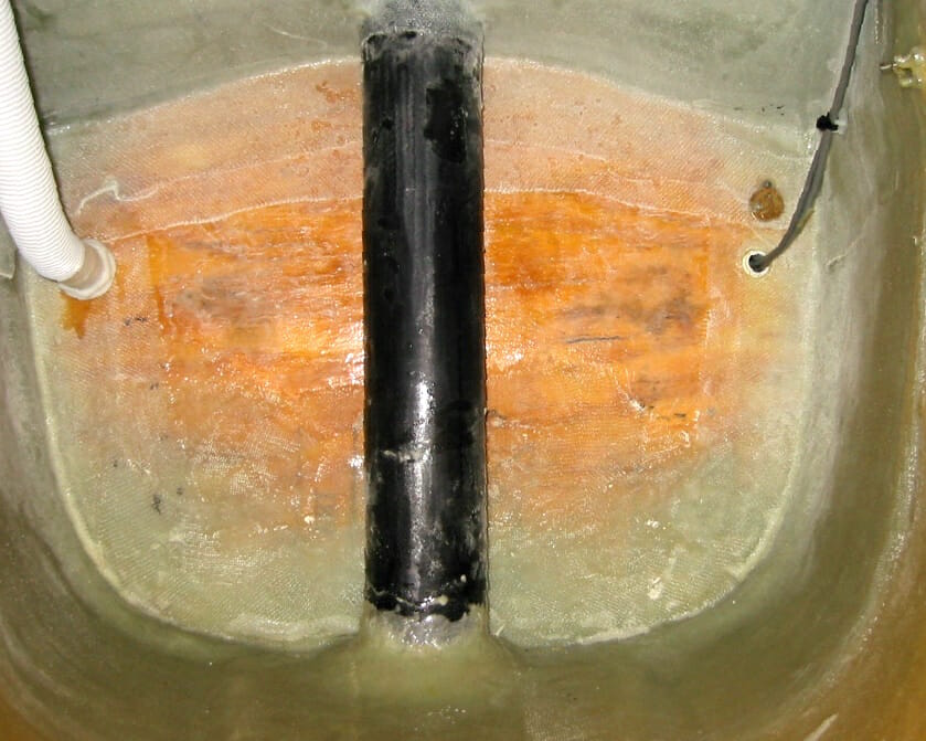
Daggerboard Trunk
For this part to make sense, I should say something else about how sailboats work. To do anything other than coast downwind with the wind astern, a boat needs a way to provide lateral resistance to moving sideways through the water. Given this, the aerodynamic lift provided by a well-designed suit of sails can propel the boat through a very wide range of angles—not directly into the wind, of course, but surprisingly close. 45 degrees is not uncommon.
A monohull takes advantage of its keel to accomplish this; that hunk of lead on the bottom is more than just a big counterweight to keep the boat from blowing over. But if we have a multihull (or a beachable dinghy, or even a sailboard), we have to provide lateral resistance some other way. This typically involves a retractable board, foil-shaped to minimize turbulence, mounted at an appropriate spot in the hull. Some boats use leeboards that pivot down outside the hull, accepting the noise and drag of a “surface-piercing foil” in exchange for simplicity and minimal impact on usable space aboard. Others go for greater efficiency with a centerboard that deploys from an internal trunk, but these eat up precious internal space and can fail catastrophically in a grounding.
We elected to try a quirky compromise in the form of a retractable daggerboard that slides through a trunk at the turn of the bilge—leaving the center of the tiny hull free for sleeping and pedaling while avoiding the splashes and general clunkiness of a leeboard. In this photo, you can see how the daggerboard is forward-angled to increase the probability of harmlessly kicking up in a grounding. (The bow is to the left, and that little fin in the lower right is part of the pedal-drive unit over on the starboard side.)
The weirdest thing about this, at first glance, is the fact that it is angled forward. This was not some dumb mistake from pulling a bleary all-nighter; it was calculated to avoid damage when I plow into something. Assuming the boat is moving mostly forward (not always the case, but one can hope), then the board will just pop up instead of attempting to pivot aft, knifing through the hull and turning an oops moment into a potential catastrophe.
To facilitiate this, we did a little trick to minimize friction. One of the more wondrous materials available from McMaster-Carr is bondable Teflon, chemically treated on one side in a way that makes the ultra-slick PTFE plastic accept epoxy. As far as I know, the only explanation for this is “magic,” but then, I’m not a chemist. In any case, it works beautifully, and whenever we needed tough slippery spots on the boat we just lopped off a suitable chunk of this stuff and glued it on. The trunk, which was molded of fiberglass around the recycled (and heavy) daggerboard from an old Nacra beach catamaran, now has little Teflon inserts in all four corners, and the sliding action is smooth.

Normally, of course, I try not to depend on hitting bottom as a way of raising the appendages. Another nice feature of the forward-angled trunk is enhanced usability: I can raise the board with one hand and park it in a little notch on the cowling. The cockpit perspective on all this is shown here with the dagger retracted, hoisted by a handle made of 1/4” braided line and a scrap of tubular nylon webbing.
The trunk itself is simply glassed into the hull and deck, providing a very stable structure that, like everything on the boat, ends up becoming a mounting surface for something else. That complicated hydraulic assembly is the rudder deployment system, and the gap between trunk and hull provides a nice place to tuck the spare paddle.
So much for the basic trunk fabrication… but there’s one critical issue we haven’t mentioned. How did we know where to put this thing? Does it really matter?
As it turns out, placement is absolutely critical. One of the many delicate balancing acts involved in sailboat design is the relationship between the center of effort (CE) and the center of lateral resistance (CLR). Screw this up, and the boat will become hard to handle, inefficient, and possibly even dangerous.
CE can be viewed as the resultant center of all the wind’s effects on anything above waterline. Obviously, this is mostly about the sail and is thus a function of conditions, but it is also significantly affected by the topsides, the arch, whether or not the dodger is deployed, laundry flapping from the antennas, courtesy flags and burgees … whatever. Somewhere up in the air over the console is a magic point that represents a big celestial finger pushing on the boat.
Similarly, CLR is the resultant of all the stuff below waterline and the drag it presents to sideways motion. Some things, like the daggerboard, are specifically designed to do this effectively, but the tendency to slip to leeward is also affected by hull shapes and the presence or absence of the pedal drive and electric thruster. The rudder is also a huge factor, but we don’t have much choice about where to put it. Daggerboard placement is essentially the only variable that doesn’t involve a lot of extra work.
Why does it matter? Picture this: if the CE is way forward of the CLR, then the boat will always try to “fall off” the wind, or turn away from the applied force and run downwind. Such lee helm can be pathological, because if you are trying to head as close to the wind as possible and for some reason (including inattention) lose rudder control, the boat will turn in such a way that the heeling forces get abruptly higher—stressing the rig and crossbeams, and, in extreme conditions, increasing the possibility of capsize. You don’t want a sneeze or a broken rudder fitting to dump you into a dangerous situation.
Conversely, if the CE is aft of the CLR, letting go of the steering will cause the boat to turn into the wind as the bow is pushed around that virtual pivot point… whereupon the sail will flog and you end up dead in the water, in irons. That may be embarrassing, but it beats hypothermia. It might seem that one would want the CE directly above the CLR, but it turns out that a little weather helm is a good feature—you can de-power without any difficulty, and turning through the wind (tacking) is easier. Of course, you don’t want the CE to be too far aft of the CLR, or you’ll burn out your arm muscles trying to fight the rudder to maintain a heading.
(There’s quite a bit more to this subject than I have indicated here. Two useful books that discuss this balancing act in greater depth are the classic Oceanography and Seamanship by William G. Van Dorn and the very approachable and practical Annapolis Book of Seamanship by John Rousmaniere.)
Some hard-core race boats actually allow the centerboard to be tuned, tilting fore and aft and in some cases even angled relative to centerline, trying to extract that extra 1/10 knot of boat speed. I’m not that devoted to performance; I just want it to work reasonably well in a variety of conditions (and not break). This was another area where we ended up integrating the advice of a lot of marine architects, taking measurements, doing calculations, and constructing an intuition that eventually allowed us to switch from pencils to Sharpies—then fire up the jigsaw to rip a long ugly hole in the beautiful Kevlar hull. The scary thing about all this is that there was essentially no way to test it until a huge amount of additional work was done and the stakes had become significant.
Fortunately, it came out just about right, although in a heavy wind there’s a bit more weather helm (tendency to head up) than I would like—and while researching a book about this, I figured out why. It is conventional wisdom among yacht designers to place the CE slightly forward of the CLR in steady state conditions… knowing that the effective CE will move aft when the boat heels. I figured that since “multihulls sail flat,” I didn’t need to take this compensatory step, and being wary of the dangers of lee helm I established the static CE/CLR relationship the way I wanted it to be under dynamic conditions. But in practice, it turns out that the phenomenon of the CE moving aft is due to mast turbulence and sail inefficiencies, and those affect a multihull just as they do a monohull. The net effect is more arm strain holding the boat off the wind when conditions are intense.
That does beat the alternative, however, and it is somewhat tweakable by adjusting a few variables (deploying a thruster, dropping the dodger, furling the sail slightly, or partially retracting the board).
OK, I think we’ve pretty well completed our brief tour of the center hull. Let’s take a quick look at the crossbeams and outer hulls!
Akas and Amas
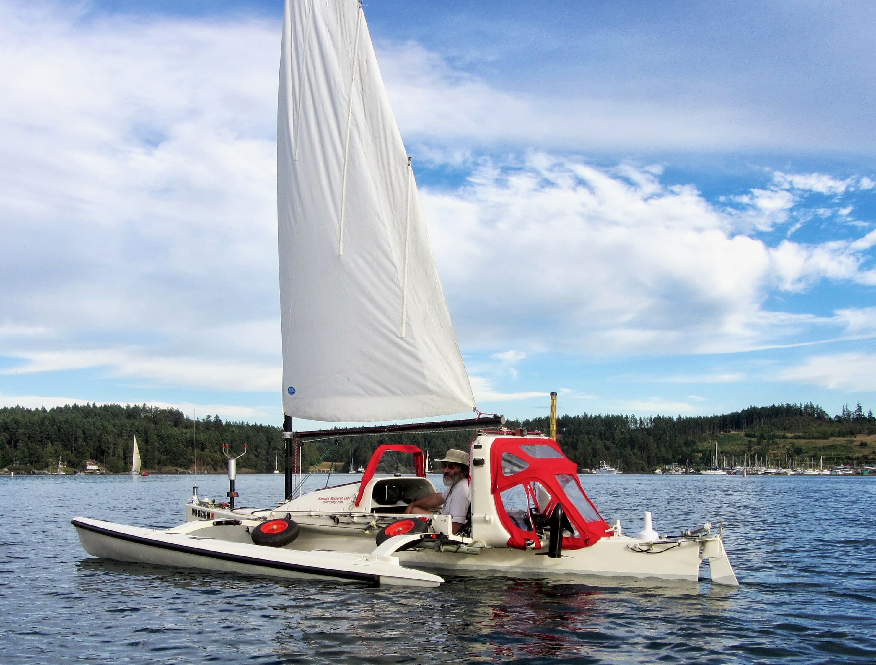
As I mentioned, we managed to save a huge amount of work by starting with an existing assembly of crossbeams and outer hulls made for the Fulmar-19 trimaran. This was familiar territory, as I had owned one in the early years of the project—all we had to do was make the Microship hull design backward-compatible with legacy components.
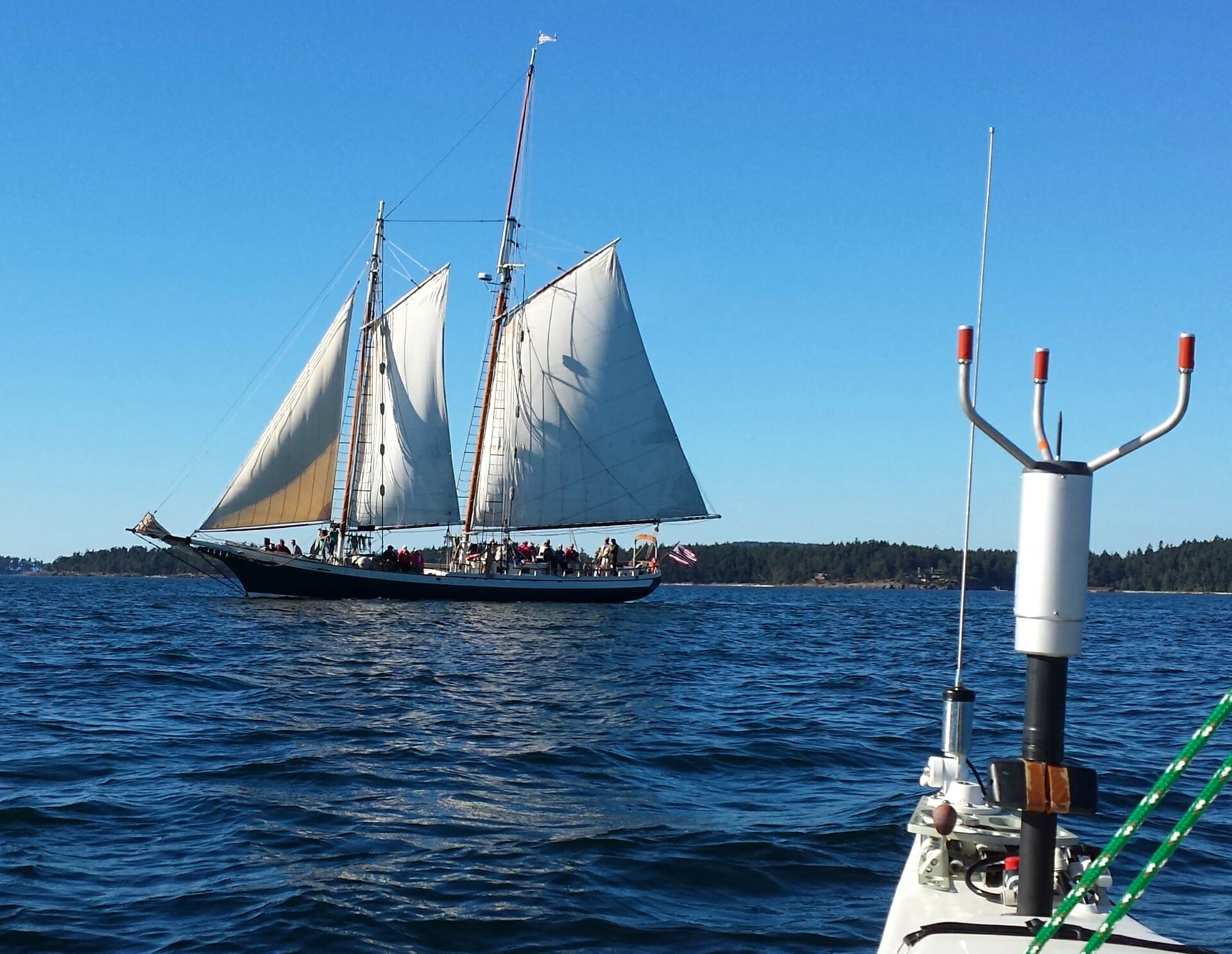
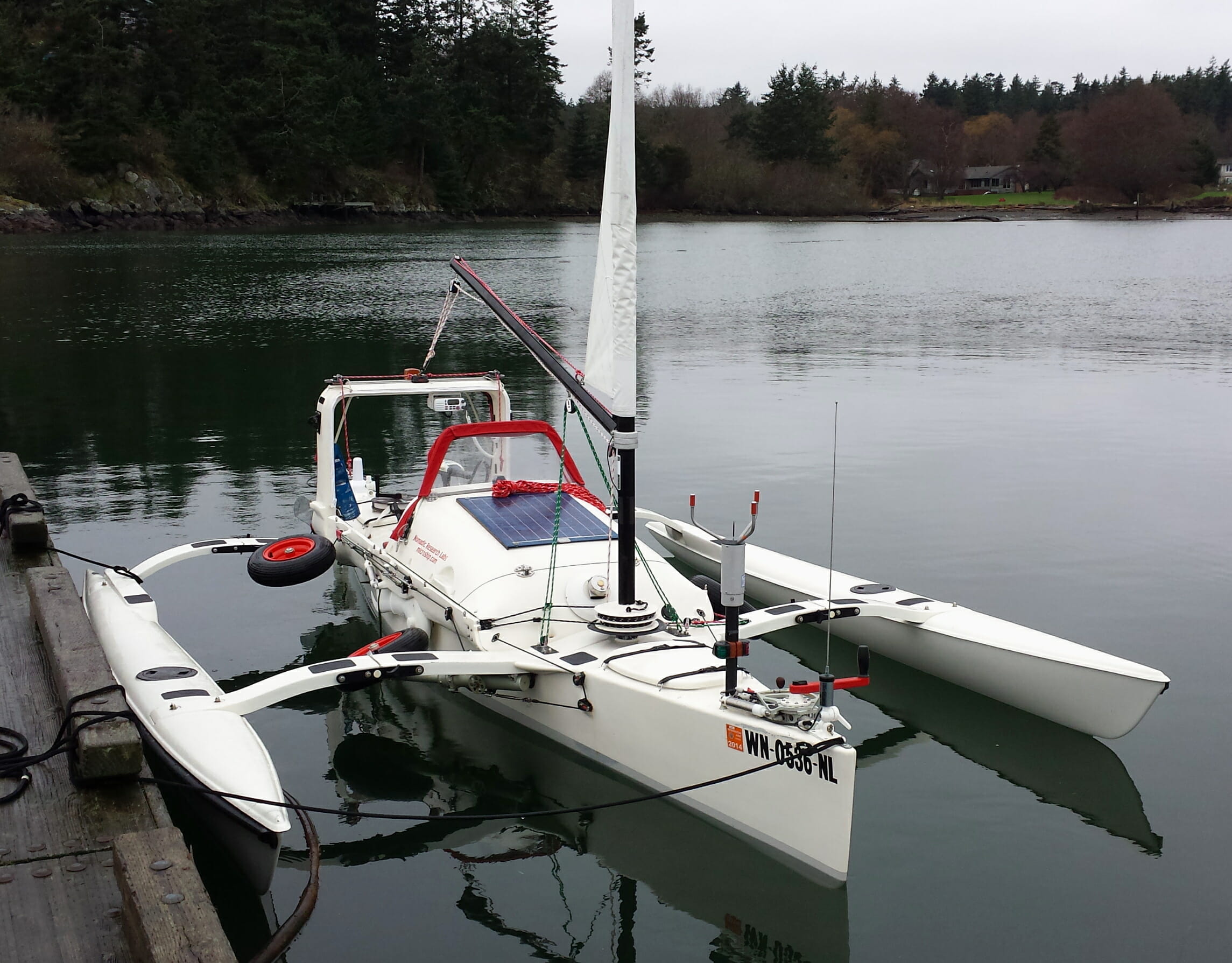
Notice in this photo that the outer hulls kiss the water rather lightly—this was intended, and it was a great relief to see that we got the dihedral about right. Actually, she sits quite a bit lower in the water once stuffed full of heavy touring gear and geek necessities, so the self-congratulation was premature. The goal is to achieve a balance: the less ama immersion, the less hydrodynamic drag from wetted surface, but if one hull is always “flying” to maximize speed, then at rest the boat will rock back and forth in a most annoying fashion. Racers err on the side of speed and fly a hull every chance they get, but my objectives are more sedate.
Another thing to notice is the curve of the akas (the crossbeams), keeping them as high above the water as possible to minimize interaction with waves. These pretty shapes don’t lend themselves to solar panel mounting very well, but it turns out that it’s a moot point anyway—there is so much flexion in the system (a good thing) that the solar array has to move independently of the outer hulls. One of the essential features of this assembly, given the complexity of those landing gear that allow haulouts and portages, is the ability to fold. In the original Fulmar, this was strictly for trailering; nobody in their right mind adds retractable, hydraulically steered full-suspension landing gear to a canoe! But as we had to do exactly that, the folding feature was doubly interesting, reducing the boat to 6-foot overall width (from the original 11) when on the road.
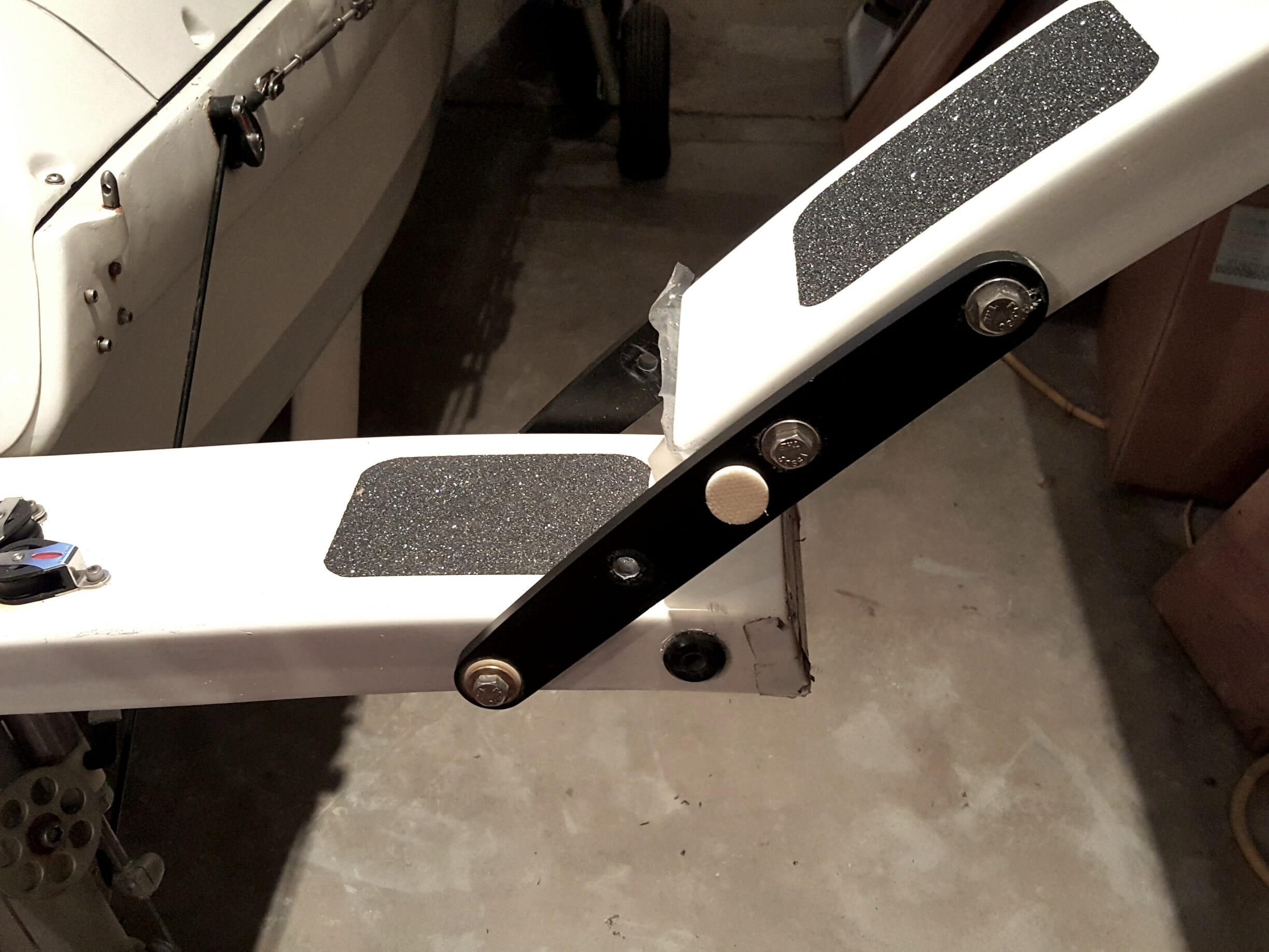
This photo shows how it works. The aka is split in the middle, with a robust pair of anodized aluminum bars forming a simple hinge that pivots around the bolt on the far left. When in use on the water, a stainless steel locking pin is inserted into the empty hole, passing through both of the bars and a couple of nylon bushings set into the flanges of the aka U-section. In practice, this isn’t the most elegant system in the world, however: however tight the assembly feels when assembling the rig prior to launch, there is still a tiny bit of slop that allow the aka segments to work against each other in rough conditions… which is why the photo shows bits of teflon tape to eliminate occasional creaks.
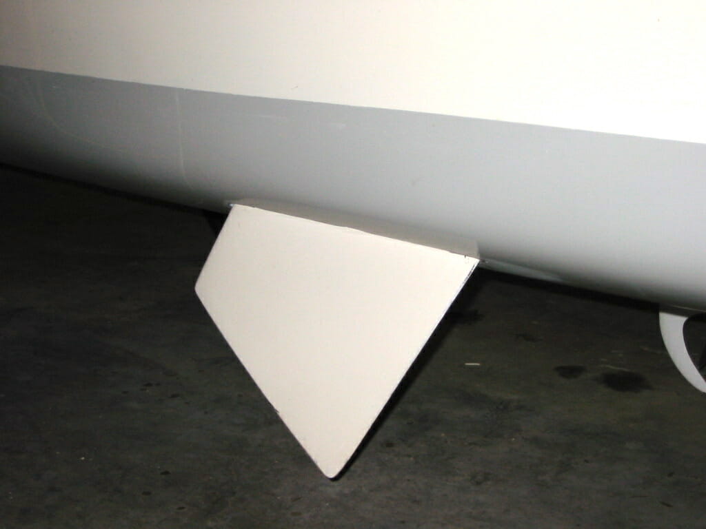
The outer hulls (amas) are simple affairs, with a single screw-on access hatch for inspection. I am often asked if I stow gear out there, but no—I want all the buoyancy I can get and they’d be a pain to reach on the water anyway. As the loads are smoothly distributed, the fiberglass layup is light and simple, interfaced to the akas by simple retaining bolts and molded nests (under normal sailing conditions, there is no focused bending moment here as there is at the junction between akas and center hull).
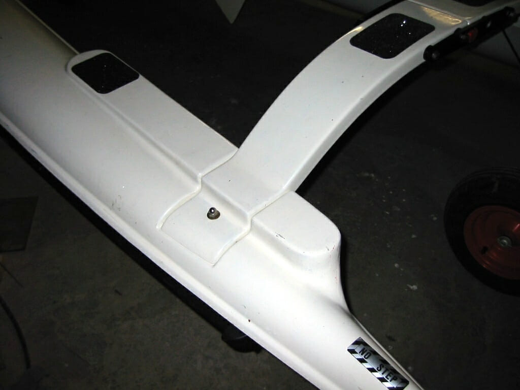
This photo shows the substantial additional surface that we glassed onto the original amas to allow better footing. Those turned out to be a lifesaver when making the journey between cockpit and dock, over and over, loaded with packs. In a somewhat related vein, being tied alongside a dock (as in a marina slip) subjects the system to additional abuse. People normally use inflatable fenders to reduce noise and abrasion, but the shape of these tiny hulls makes that ineffective—they float up, move around, and otherwise do all they can to avoid being useful. If you look closely at the photo, you can see part of the solution: a black rubber extrusion made to cushion tractor-trailer rigs backing up to loading docks.
On the Road
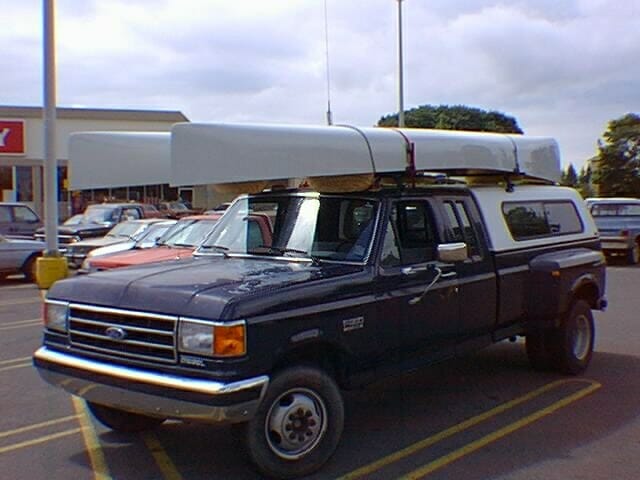
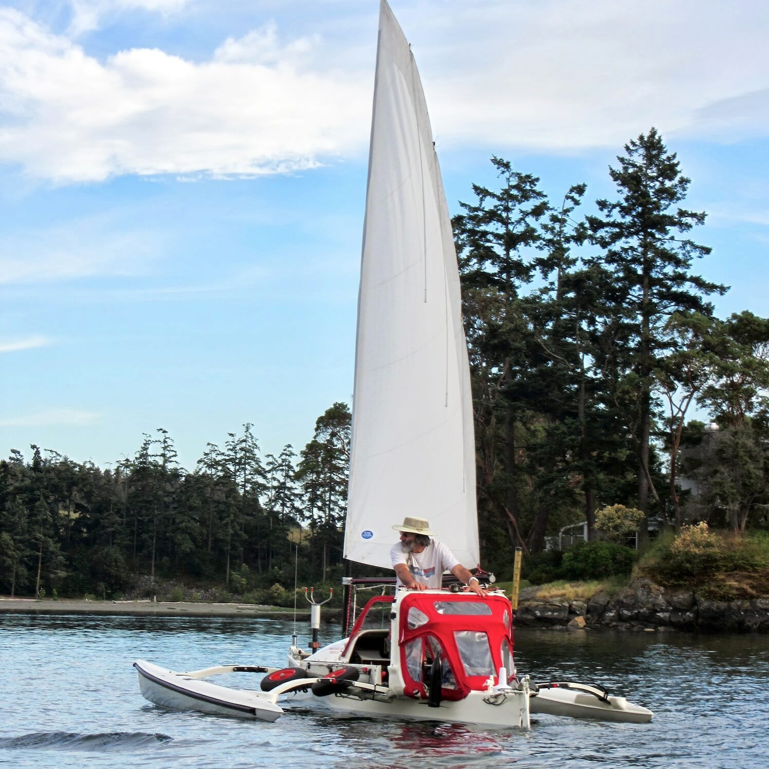
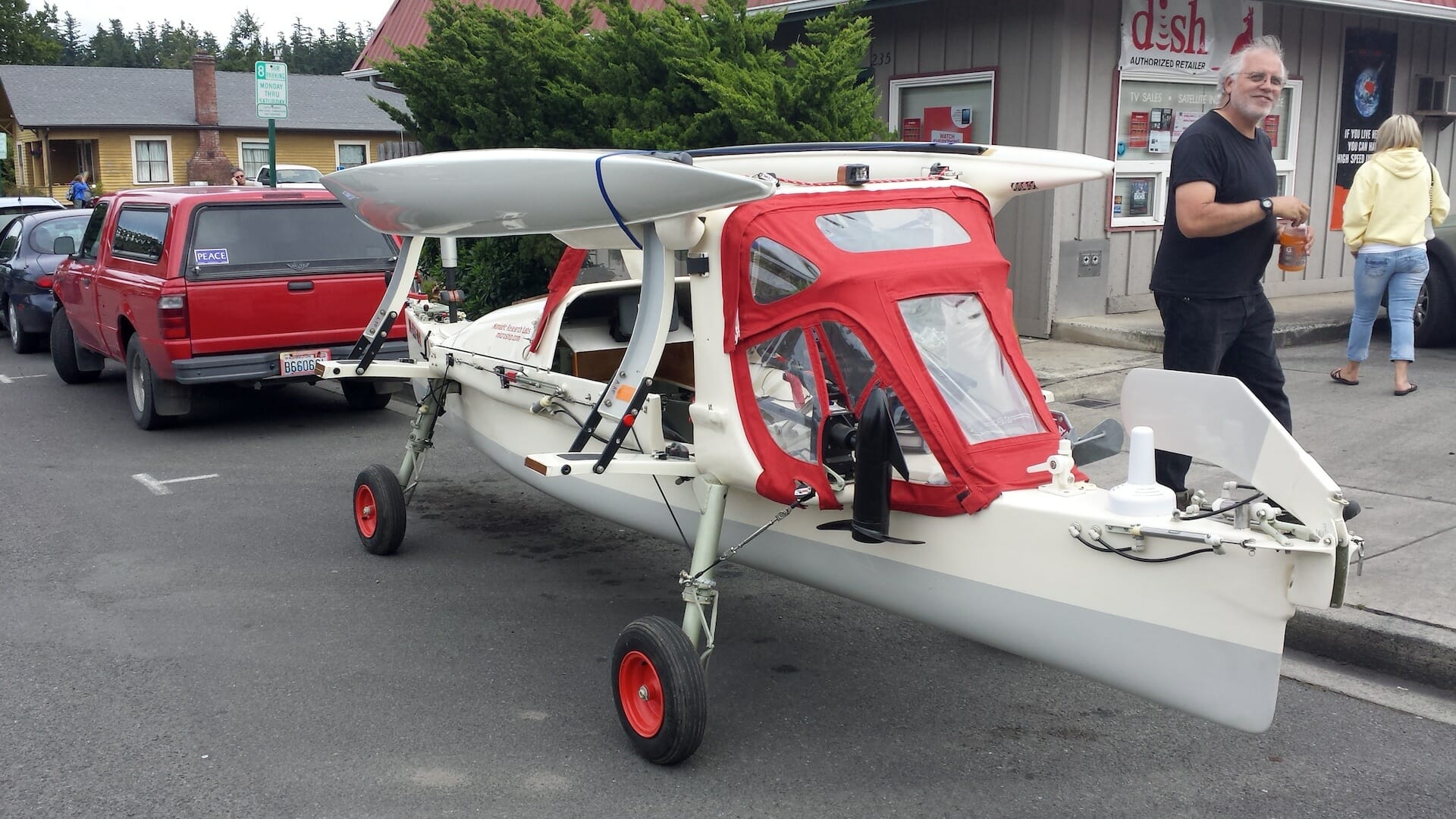
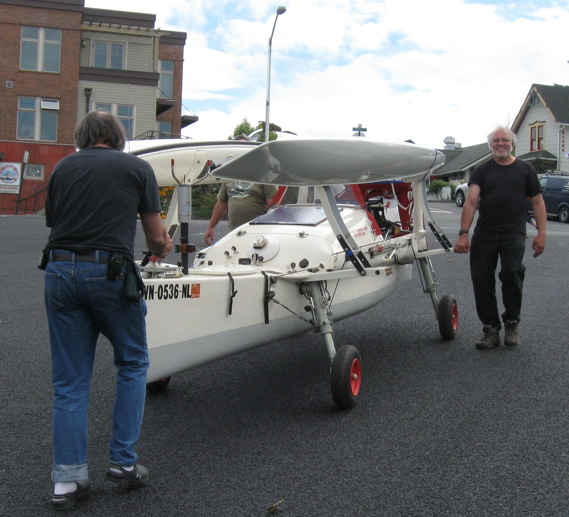
That pretty well completes the basic substrate, though of course there’s quite a bit more that turns it into the Microship! The landing gear are worthy of another whole article of this scale… they were a huge project, but allowed the boat to be launched and retrieved without a tow vehicle. Here she is emerging from a test sail in 2015, and again at the end of the summer of 2013:


And, of course, meandering through the town of Friday Harbor with the amas folded…
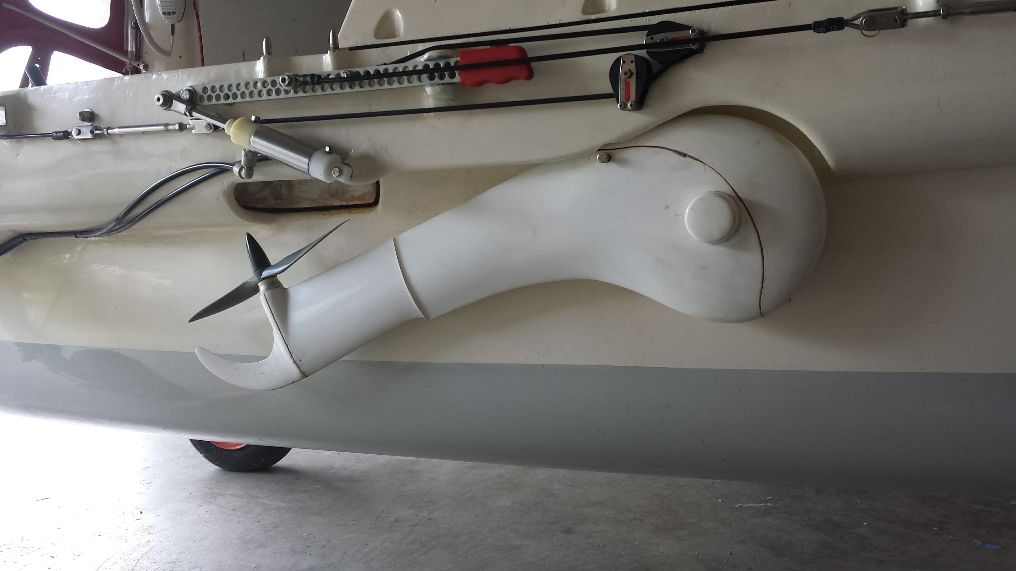
And the exquisite little SpinFin pedal drive unit, built by Bob Stuart:
But those additional details, along with hydraulics and rigging, are topics for another article. (I did a photo essay of the electronic systems that were developed in parallel with this, though of course those are pretty much obsolete by now!) One more teaser… this photo shows the enclosed electronic equipment cowling along with the 480-watt solar array….

Where to Now?
I’m writing this in 2016, revising an earlier version I did on 2004 for the Inside Microship book project (never completed), and the boat is sitting quietly in a rented shop space two miles from the marina where I live aboard Datawake. I have planned to crane-launch the Microship from the upper deck, fulfilling my dream of “scaled technomadics,” but I’ve decided that it would just be too complex…. that’s a job for something light, rotomolded, and turn-key.
So it is getting to be time to find a worthy successor to take over the Microship project… whether for an expedition as I had originally planned while building her (across the US via the Missouri River and then around the Great Loop), as a substrate for intensive geekery and data collection, or something I have yet to imagine. This article, and others to follow, are being added to the archives to provide useful background information for anyone contemplating such an undertaking.
I am deliberately not mentioning a price or other arrangements… that will depend entirely on who takes this on, what kind of public exposure it will generate, and how much I need to be involved. I welcome proposals…
You must be logged in to post a comment.