
Articles by Bob Stuart
I’ve known Bob since Expo ’86 in Vancouver, and was very fortunate to have had his direct involvement in the Microship project from 1998-2002. He is a human-powered vehicle designer, composites guru, painstaking craftsman, and the brains behind the Spinfin pedal drive that we used on our pedal/solar/sail micro-trimaran.
Here are Bob’s original articles about the Spinfin, Coroplast HPV body construction, and his famous Car-Cycle. I’m honored to be able to host his work; the Microship reflects Bob’s hands-on design and fabrication skills over a period of three years, and I have a lot of respect for him.
— Steven K. Roberts, April 2017
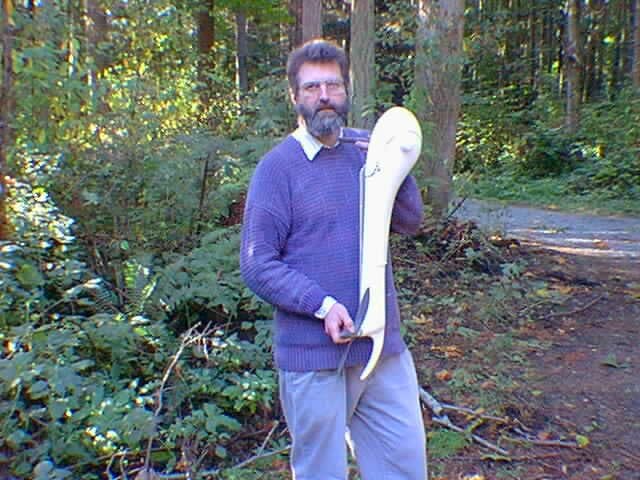
The Spinfin Pedal Drive Unit
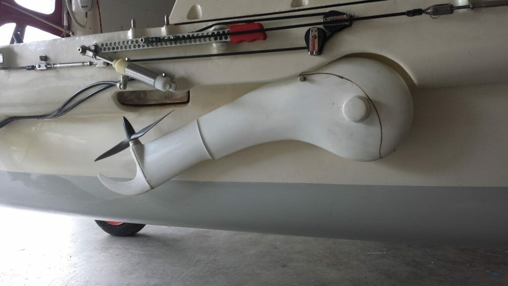
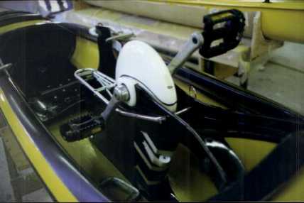
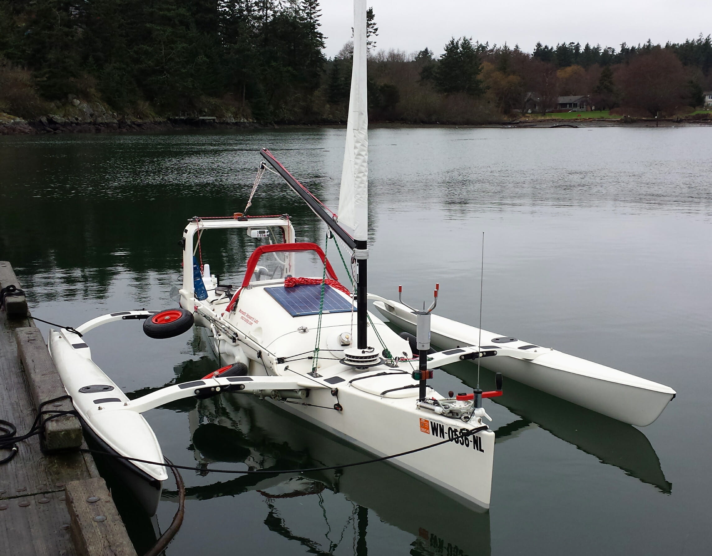
The Spinfin drive unit shown here is the basic unit that can be mounted beside a hull with the drive shaft as shown for Steve’s Microship, or installed in a daggerboard trunk in like fashion with standard bike cranks and pedals mounted directly to the unit.
The combination of drive unit, lifting lever and drive trunk is available for easy installation into many types of boats. In use, the propeller is below the pedals, and when up and parked, the unit is near horizontal, with the pedals forward, and the prop accessible. The new drive units have been refined after five years of experience in many different conditions.
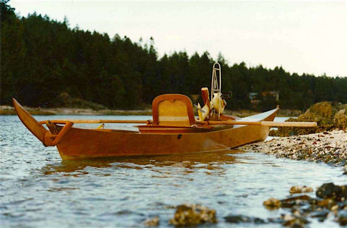
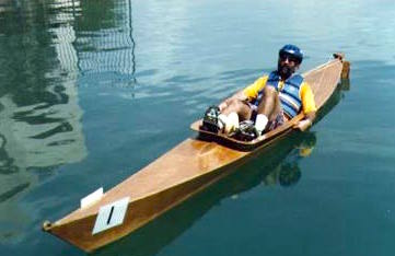
This arrangement was developed on Lambordinghy, converted from a Pygmy Kayak kit. She is the 1996 world champion recognized by the International Human Powered Vehicle Association. A similar kayak conversion was certified at over 9.5 knots in a sprint, with a small but strong novice rider. Gordie Nash has an even faster boat using a lengthened version of this drive in a trimaran with the main hull derived from a racing shell. She runs at seven knots on the open ocean for an hour or more, winning races against sliding-seat scullers.
With such an efficient drive system, you can get high speed or effortless cruising in any small boat. The drive unit features five ball bearings and a single loop of twisted chain for simplicity and minimum friction. The gear ratio can be either nine or ten to one. Many available propellers can be easily changed for different conditions. Each is suitable for a wide variation in effort; there is no need to change props between sprinting and cruising. The standard drive trunk and its lifting lever allow the unit to be raised in one second with one hand, for beaching or weed removal.
The drive unit is easy to use and requires little time for maintenance. Sealed against water entry, it has an oil bath for the chain. It can sustain major collision damage and still work indefinitely, and is easy to overhaul far from civilization if necessary.
New Proa-Style Boat
On our new boat, the drive unit will mount beside the main hull. The offset thrust will be balanced by a single outrigger. This leaves the cockpit more open and further reduces the chance of damage from grounding. It also provides a much narrower main hull for higher speeds, stability for sail carrying, and provides a place for a trampoline for passengers or camping. The main hull is twenty feet long, with a semi-wave piercing bow. It has generous freeboard amidships around the single open cockpit, with fine ends for light weight. We will provide kits for stitch and glue construction or completed boats. The offset drive and special pedal cranks will be available separately.
Pedaling uses the biggest muscles in the body, minimizing fatigue, and leaves the hands free. A person of average fitness can keep up with very athletic kayakers all day, in greater comfort, and feel much better all evening. With the outriggers often used, there is no problem with stability to worry the novice. Pedaling can get you wherever kayaks go with more attention to spare to enjoy yourself there. In a dinghy, our drive unit will pamper you with easy speed, and a view ahead. There is no awkwardness over clearance for oars, or the weight and hazards of outboard motors.
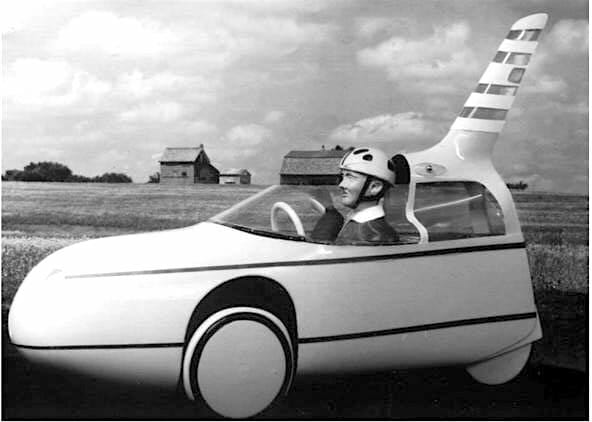
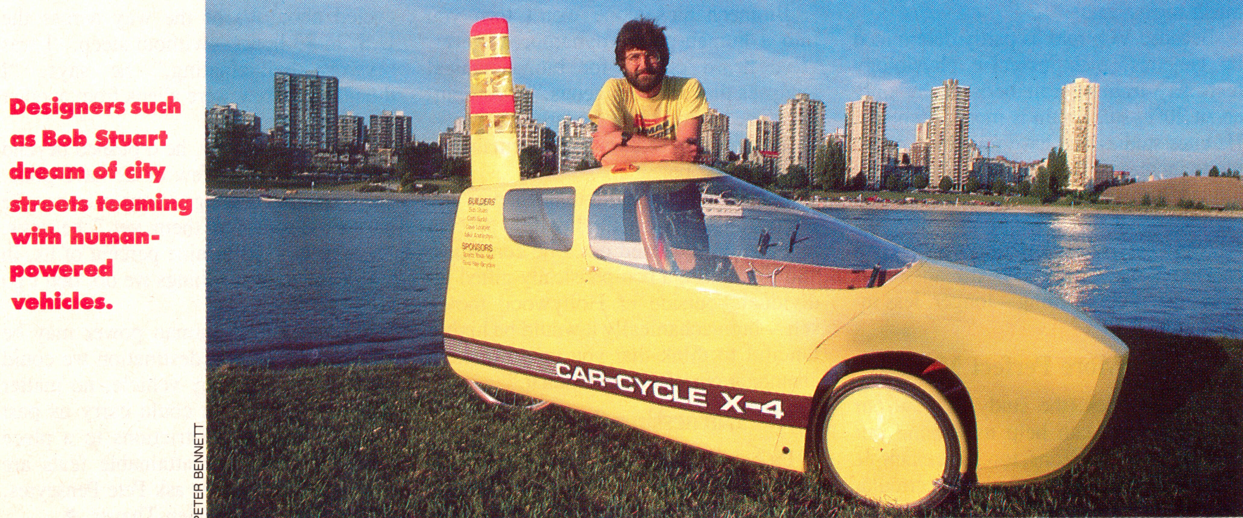
The Car-Cycle
The Car-Cycle X-4 was built as an experimental prototype in 1986-87. In ’88 it won two second places and one third place in the IHPVA Practical Vehicle Championships in Visalia, California. In ’96 it won that event outright in Las Vegas.
The X-4 was built with minimum investment to test its general configuration and proportions. Many minor features help to make it as car-like and convenient as possible. The goals of the overall packaging were to allow room for an adult, child and two grocery bags, to make it narrow enough to go through a standard door, to be tall enough for confident riding in heavy traffic and to keep the shape streamlined.
The major technical innovation also tested is the frame and suspension made of continuous fiber composite parts providing many functions. Just six moldings of Kevlar™, fiberglass, and epoxy resin comprise the seat, frame, springs and suspension arms. By incorporating suspension in the frame members the number of parts was almost unaffected, and the total weight was actually reduced since less strength is needed to withstand impacts. Much thought went into the suspension geometry and frequencies, and the test riders have all found the ride amazingly comfortable, even when going fast over a speed bump.

Steering is by side sticks which have about two feet (60cm) of travel, so the action is not twitchy even at high speed. The right hand grip has a lever connected to both front brakes. The left has many functions. Starting from the top are the turn signal switch, the horn button, a lever to mist water onto the rider’s legs, shift levers for the wide range derailleurs, and the rear brake. Reversing is accomplished by gripping the right tire through a slot in the fender and pulling.
The height and width specifications made the trike likely to fall over in hard cornering, so the doors were arranged to allow the rider to lean to the inside for better balance. With the brakes on, trikes with two front wheels gain stability and use up some traction, so they will slide rather than roll. In two real-life traffic emergencies, handling has proven adequate to avoid an accident.
Many of the features added to make the Car-Cycle more civilized are electrical gadgets run off a 12V motorcycle battery. Lighting includes a powerful headlight, a brake light, turn signals on the roof visible to front and rear, and three lights in the “Safety Sail” tail fin which flash up and down in time with the pedals, imitating pedal reflectors on bikes.
There is also a fan for cooling the rider and/or clearing condensation from the windshield. A manual windshield wiper clips over the top of the polycarbonate windshield when needed. The overall ventilation is regulated by removing or replacing a panel in the nose. With the panel on, it is shirt sleeve temperature inside when freezing outside. The next version will have a convertible top for hot weather riding. On rainy days, the fairing is most welcome.
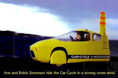
The “Safety Sail,” a large tail fin, is intended to replace the flag sometimes used on bikes. The fluorescent stripes and lights substitute for eye-catching flapping while keeping drag low. In a crosswind, the fin can swing into the wind and act as a sail, as well as keeping the trike balanced to keep going straight.
The main door uses the windshield for a hinge and allows reasonably easy access. A rear view mirror is mounted to the inside of the windshield. A standard bike speedometer is used. Behind the seat you can have either a cargo box or a standard bike child seat. About half the kids encountered would not get in when first offered a ride. Most of the others would not get out afterwards. Both occupants are protected by a roll bar extending up from the main seat back and providing a head rest. Currently only the child has a seat belt, but two could be used.
The bodywork around the rider is made of fiberglass and Kevlar™ for crash protection and ease of molding. Coroplast, an extruded polypropylene material resembling corrugated cardboard, is used for front and back body sections. This is not much stronger and stiffer than it needs to be to smooth the airflow, but is light and tough, shrugging off casual blows.
The overall performance is quite exhilarating. The speed advantage over a regular bike is about 20% with the vent open, and 30% with it closed. Construction expediencies added about 40 lbs (18kg) to the target weight of 60 lbs (27kg) so it always feels like a production version with lots of luggage. The extra weight, plus the streamlining lead to very interesting riding in rolling terrain. Momentum will carry you up a hill about three times farther from a preceding descent than it will with a bike, so average speeds are much the same as on the flats. On the other hand, in city traffic, the rider tends to put out short hard sprints followed by long periods of coasting. An electric booster is planned to even out these efforts and keep the speed more constant among hills. ESPN, the sports network produced a very popular show on the IHPVA Championships in ’88, and devoted five minutes to the Car-Cycle, calling it the BMW of human powered vehicles. It was also featured on several other TV shows. Of the extensive press coverage, the best was a two-page spread in Bicycling Magazine in April ’93.
None of the coverage led to the hoped-for partnership with an established manufacturer or major investor. The opportunities offered led to work on pedal boats, which is now approaching profitability for the second time after loss of a facility. The designer, Bob Stuart, is willing to help with serious attempts to produce more efficient vehicles.
Car-Cycle X-4 Integrated Suspension
The Car-Cycle X-4 was built to test its general configuration and proportions, to experiment with a frame and suspension of continuous fiber-composite construction, and to demonstrate the attractiveness of a vehicle with many accessories contributing to its practical value. Despite crude and cheap detailing, it won considerable acclaim and interest from prospective customers. Most of the design features work well; cornering stability may need major revision. The integrated frame and suspension are quite successful, and can be readily refined to eliminate two problems. The ride quality is particularly good, and the methods used to achieve this are examined in detail. Suggestions for curing deficiencies of the X-4 in a subsequent development are included.
General Concept
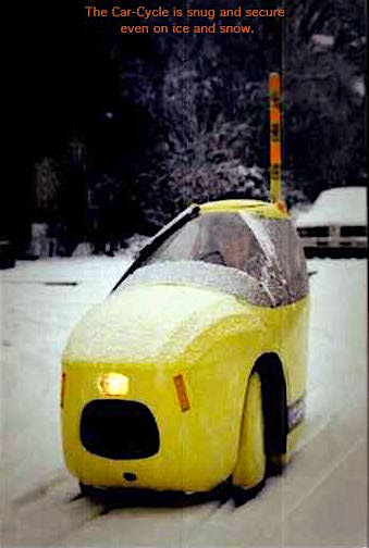
Almost from the beginning, the IHPVA Speed Championships showed that racing velomobiles also had as fringe benefits more comfort, weather protection, potential enclosed luggage space, and three-wheel stability, especially useful for icy Canadian winters. After much thought and study, the Car-Cycle X-4 was designed to combine speed, comfort and practicality.
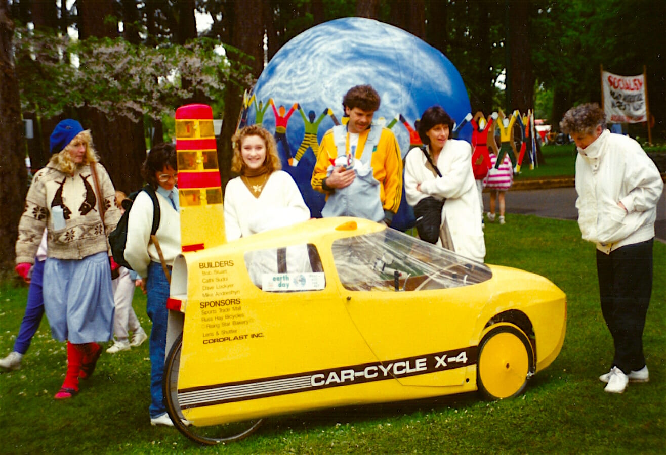
The Car-Cycle X-4 was built by a group of friends including Dave Lockyer, Cathi Sudol, and Mike Andreishyn as an experimental prototype in 1986-87. The chassis was displayed at the International Human Powered Vehicle Championships held at Expo ’86, the world’s fair held nearby in Vancouver, on the west coast of Canada. In ’88 it won two second places and one third place in the IHPVA Practical Vehicle Championships in Visalia, California. In ’96 it won that event outright in Las Vegas.
The X-4 was built on a minimal budget to test its general configuration and proportions, and to demonstrate many minor features that make it as car-like and convenient as possible. The goals of the overall packaging were to allow room for an adult, child and two grocery bags, to keep it narrow enough to go through a standard door, to keep the shape streamlined, and be tall enough for confident riding in heavy traffic. The height and width specifications made it likely to fall over in hard cornering, so the doors were arranged to allow the rider to lean to the inside for better balance.
The major technical innovation also tested is the frame and suspension made of continuous fiber composite parts providing many functions. Just six moldings of Kevlar™ fiberglass and epoxy resin comprise the seat, frame, springs and suspension arms. In many places where a mechanical hinge would normally be used, a fiberglass tube frame member is just flattened out to provide both a spring and a hinge. The front suspension is similar to a normal dual A-arm arrangement, with integral springs instead of inboard pivots. Ball joints are used near the wheels. The design is modified to provide extra heel clearance via a semi-leading upper arm, a floor surface on the lower arm, and aerodynamic trail for the wheels.
Chassis Construction
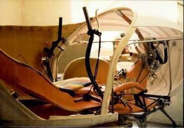
Construction of the fiberglass parts was fairly straightforward. The seat was formed by putting a couple of layers of resin-wet Kevlar™ cloth in a garbage bag, and molding it between a rider and a bean-bag chair. The resulting comfortable shape was then suitably reinforced to make a large tubular structure with leaf springs projecting forward to short control arms. One center spring extends forward just below the seat, and two side springs come off 63 mm (2.5″) lower, their rear extensions providing a lower seat surface for use when leaning to the inside of a turn. This can be seen in the illustration on page 9 of the manuscript.
The main frame was made by carving a large foam blank made from layers of Styrofoam insulation. This was then cut up in the area of the suspension attachments to allow insertion of internal reinforcement bulkheads. These were laminated to the small sections cut out, and then the main foam blank was reassembled and covered with appropriate layers of Kevlar and fiberglass, usually to a minimum of .8 mm (.03″) thickness to forestall buckling. Kevlar was used as much as possible for its lower density and greater stiffness. Glass was used for areas with high compression forces and where sanding was required to finish the shape. The foam was subsequently removed from much of the structure.
The rear fork is also a large section fiberglass tube partly enclosing the chain. It merges into a flat leaf spring made of many layers of unidirectional Kevlar, woven Kevlar, and unidirectional S-glass. Unfortunately, being only 6″ wide this spring gets twisted during cornering, and if bumps are encountered, can cause the rear wheel to skip sideways. This is probably the worst vice of the chassis. On the next one, I would use two springs mounted farther to each side, and not bother enclosing the chain in the fork.
The spring is carefully located relative to the drive chain. Under tension, the chain should pull down on the rear wheel just enough to compensate for the normal squatting at the back from acceleration. The plane of the drive chain between the last idler and an intermediate freewheel cog intersects the plane defined by the spring and rear axle, directly under the center of gravity. This was reasonably successful. The spring was molded with a slight curve, to come flat under load.
Carbon fiber was rejected, perhaps hastily, as a spring material because it is so stiff that it does not move much as a spring; glass stores more energy per unit of weight. In its favor, carbon has a much higher fatigue life, so more of its initial strength can be used, and a thin layer of it in compression can put a somewhat thicker layer of Kevlar or Spectra™ into tension, where they excel.
Most of the high loads are taken in and out of the chassis and suspension members by metal fittings. For instance, at the front an old steel bike donated a bottom bracket. The down tube was modified to support the bodywork, a stub of the seat tube was left for the front derailleur, and the chainstays were cut down to about 12 cm (5″) long. They were then split along their inside edges and peeled open flat, and hammered to conform to the shape of the foam chassis blank. The edges were then ground sharp to reduce the stress riser at the change of material from metal to fiber. After careful cleaning, the steel bits were bonded in with the laminate.
The wheel springs are attached to the chassis with rows of flat head machine screws in molded holes, mating with tapped strips of steel molded into the frame. Special thimbles were brazed up for the ball joints and seat suspension pivots. The front suspension uprights and brake supports are all of brazed tube, as they need so many metal features in such a small area.

Suspension
Much thought and planning went into the details of the suspension system. A proper suspension is much more than just a way of avoiding the worst impacts and discomfort of an unsprung vehicle. A really good ride is a positive experience, encouraging the rider to tackle difficult terrain at speed, confident of maintaining traction and poise. It also is very kind to the vehicle, making it much less prone to break or shake apart even if more lightly built than an unsuspended example. Thus, by incorporating suspension in the frame members, the total weight can be reduced.
On sporty cars, dual A-arms are popular for their precise control of wheel camber. With narrow tires and surplus cornering traction camber control is much less important. Instead, the geometry was planned mainly to give minimal friction from sideways scrubbing on bumps. The difference is subtle; either goal requires a low roll center. Determining the location of this virtual center is beyond the scope of this article, but you can safely copy almost anything used for cars except swing axles.
Compared to motor cars, a Velomobile has one advantage but two liabilities in riding comfort. The good news is that a rider who is athletically active is comfortable with a much harsher ride than a sedentary driver. One problem is that the athlete must be firmly supported using less area of the body, and is more sensitive to being tilted to one side. The other problem comes from the size of the vehicle. Most people will tell you that a heavier car gives a better ride, but actually it is the size of heavier cars that is most advantageous. Hitting the same bumps the smaller vehicle will tip and pitch more, especially with a relatively higher center of gravity.
Heavy cars often have some advantage by having a smaller percentage of their weight unsprung, but in that respect we are even farther ahead with the narrow tires we use for low rolling resistance. On the other hand, those tires give a harsher ride, so we would like to have more rubber isolation of the suspension and sound dampening material. Unfortunately, the smaller vehicle can ill afford the vagueness of rubber mountings or the weight of sound absorbing insulation.
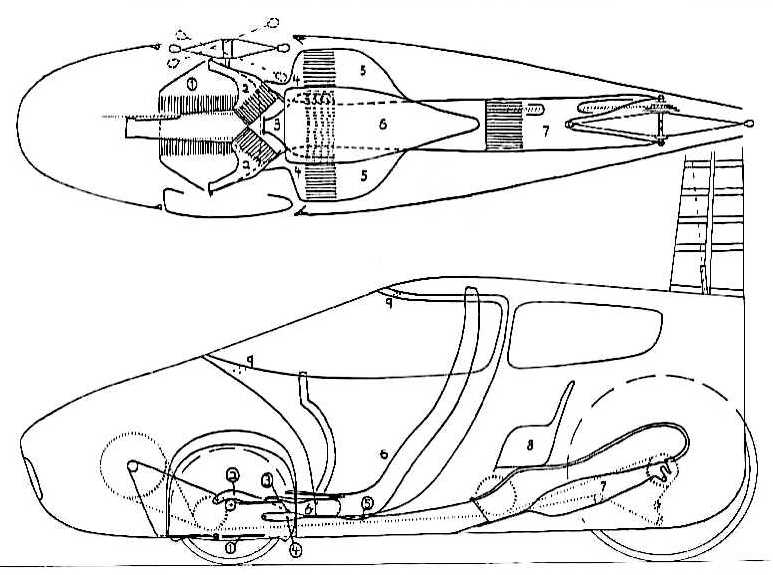
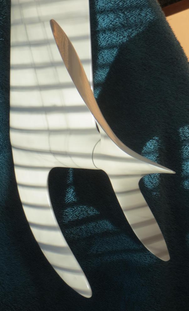
Key to Drawing
- One-piece lower A-arms and springs
- Upper A-arms and springs
- Upper seat suspension control arm
- Lower seat suspension control arms
- Low, side seat sections
- Main seat back
- Rear fork
- Child seat
- Two (only) mounting points for the assembly of the windshield and two doors
(Close parallel line patterns depict spring-pivot areas.)
The Car-Cycle design handles this situation by having two levels of suspension. Between the road and the rider there is the expected wheel suspension, but there is also a seat suspension. On the chassis alone, the ride is very stiff, like an empty truck or a vintage racing car. This keeps the pitch and roll motions of the chassis to half the amount they would have with a normal spring rate. The rider only feels the hard ride with the feet, which are well used to impact. The torso is supported by the seat, which rides on a separate parallelogram. We are fortunate that a recumbent rider requires firm support for pedaling only fore and aft, so bumps are easily accommodated. The seat suspension finishes the job of keeping the rider comfortable without affecting overall pitch and roll.

The seat is visible at the upper left, with its upper and lower springs below. The small circle in the middle is the lower seat control arm pivot. To its right we see the row of clothespin dampers rubbing on a tube attached to the lower A-arm. The arc above this is the upper A-arm, extending from its spring on the left to a ball joint on the right. The ball joints support the upright, with the steering rod below the axle holder.
On this prototype, no attempt was made to isolate the suspension with rubber elements to isolate road noise, and quite a bit of rumble winds up resonating in the bodywork. A proper isolation is mechanically complex in many cases unless taken into account from the earliest planning, where it will veto many otherwise excellent designs. It tends to introduce a weak interface into otherwise high stress areas. It will also almost unavoidably lessen the precision of the steering, giving some reduction of control and increase in rolling resistance. For the best isolation, we should have the sound damping material as close to the hubs as possible, and before any large resonating surfaces are encountered.
Between the drawing board and final vehicle, a lot of variation crept into the Car-Cycle. The effect of the epoxy resin on the spring rate of the Kevlar (TM) and fiberglass springs was neglected in the calculations, so the springs were much softer than anticipated. Also, the seat springs were greatly softened by a workshop accident. Thus the seat suspension was often bottomed out, but this gave more headroom, an advantage when the trike was transferred to me from the shorter original owner. The design had enough in hand that the only big problem brought on by these changes was the excessive roll in the corners. Ground clearance was reduced, but was still ample for speed bumps. Indeed, the trike could hit these at speed with much less distress than anything but a big Citroen, probably because of the low unsprung weight. People accustomed to unsprung bicycles are easy to please, or even amaze, and I got only compliments on the comfort from test riders.
Roll resistance was only provided by the basic springs. It could have been improved by an anti-roll bar. This is typically a lateral torsion bar which tends to lift the wheel on the opposite side of a car when either one rises. A much more elegant arrangement, more in keeping with the simple integrated fiberglass suspension is now in use by Fiat and General Motors. GM uses a transverse fiberglass leaf spring attached near the wheels with another two mountings some distance apart to the chassis. Thus as one wheel rises, the spring bends down between the chassis supports and this tends to lift the opposite wheel. Of course this will work just as well with our spring-hinged suspension arms as with separate control arms.
Normally, a designer tries to get a vehicle to have almost the same frequency in bouncing, pitching and rolling, and to remain fairly level as it goes over bumps. Having a center of gravity that is higher in proportion to the width and length than an average car, the Car-Cycle will naturally tend to rock and pitch slower, other things being equal. The bi-level suspension is a great help here, as it makes the wheel springs harder, raising those frequencies. The pitching comes out about right, and a strong anti-roll bar function can bring the rolling rate in line.
As to the level ride, Velomobiles in general are not favored, and the Car-Cycle is right out of range. The general principle used is to make the front springs softer than the rear ones. When the front wheels hit a bump, the front of a vehicle gets some upward momentum. A split second later, the back wheel or wheels hit the same bump, and that end starts to rise. With stiffer springs back there, the motion is quicker and catches up to the motion at the front, so both ends come down around the same time.
Having a short wheelbase reduces the difference to be accommodated, but a lower road speed increases it. With its bi-level suspension, the Car-Cycle has very high wheel frequencies, and so when we try to add and subtract wheelbase-travel times from them, the front end gets too soft to properly resist roll and the back gets almost solid. Consequently, the back was made only a bit harder, so the motion tends to go level, but does not usually get there before the motion is damped out except at very high speeds.
A stiffer rear spring can be handy for carrying loads, but then the normal ride deteriorates. To avoid this, the Car-Cycle luggage and child carrier is mostly suspended on its own separate springs. The geometry is such as to almost cancel any squat from the carrier load, providing automatic load leveling. This is not ideal either, as the motion of the carrier is amplified when it is lightly loaded, so a single carton of eggs gets a rough ride, but then small loads can be carefully packed.
Unfortunately, there seems to be no easy way to incorporate automatic load leveling into the main geometry to compensate for the wide range of adult body weights. A manufacturer might offer machines intended for different riders, possibly with a size variation to benefit smaller people. Alternatively, we could just accept a harsh ride for light people, and a soft, low one for heavy ones. Adding adjustable springs could also be done, though this might spoil the current elegant simplicity.
Another nice feature of a suspension system is that it can reduce rolling resistance. First, it allows use of a much lighter tire construction, which helps a lot. Also, as a wheel rolls up a bump, it stores energy in its spring, much of which is recovered as the wheel rolls down again. Regular bikes do this on hills, but with suspension the effect works on smaller and sharper features. Unfortunately, suspension systems need dampers, or shock absorbers as they are sometimes called. These keep the system from prolonged bouncing , which is uncomfortable and can even get out of control if the frequency of the bumps matches the resonance in the springs.
The damping is usually done by hydraulics, with more resistance on the return stroke. The Car-Cycle uses friction devices. For each side of the front suspension, five common clothespins with wooden jaws and a steel spring were clamped on an a 10 mm (3/8″) aluminum tube. Then another piece of aluminum flat stock was glued to the backs of the jaws on one side. When this had set, one could slide the tube through the jaws, but with difficulty. The ends of the tube and flat stock were trimmed appropriately, extending in opposite directions and ending with a small hole for a hinge pin. Similar constructions were attached to the seat and rear suspension also with one end on the chassis and the other on the moving part. The friction was adjusted with added rubber bands to augment the springs.
Later, the multiple separate jaws were dispensed with, and just two V-grooved wooden sticks held around an aluminum tube by rubber bands were used. The advantage of these systems is that one of the jaws would ride along with the tube some distance as the springs came to the right angle to make it slip. Thus, for small motions, only one jaw was rubbing, so the friction was halved. This way, more of the momentum of the trike is preserved over the almost constant small bumps in a road. For large motions affecting comfort or control, full damping is automatic.
Mechanical Parts
The front wheels use Moulton tires and rims re-drilled for 36 spokes, with Phil Wood wheelchair hubs. The rear wheel has a 700 c rim on a widened steel Campagnolo hub. The transmission was made of available used parts except for the Moulton freewheel, a 11X32 7-speed cut down to 13X32. Originally, triple rings were used on the cranks, but this was reduced to two to reduce chainline problems with the front idlers, which were close to the crank and of large diameter. Special large idlers were also used near the rear spring to reduce the friction associated with more degrees of chain wrap at each idler tooth. The front idlers change the chain direction by 45 to 50 degrees, and the reaction forces were too much for the original single ball bearing on the power side.
The brakes are cable-operated caliper rim brakes all around. Support for the front ones was not far away, with 8.5″ radius wheels less the 2.5″ “kingpin” offset forward. Very short reach Weinmann sidepulls were used. At the front, one was flipped with special hardware to keep the cable runs inboard. Both front brakes are operated by the right hand. A mountain bike brake lever modified to pull two cables replaced the original light lever with separate cable splitter. Mathauser pads were used for wet braking performance.
With the brakes on, trikes with two front wheels gain stability and use up some traction, so they will slide rather than roll. In two real-life traffic emergencies, handling has proven adequate to avoid an accident. Under hard braking, there is very little weight on the rear wheel, so the rear brake is only used for parking and emergencies. Rear wheel skids dumped two early test riders of the bare chassis in a parking lot before the rear brake lever was relocated.
The steering levers are mounted to the seat and move up and down with it. Originally, they were connected to the chassis through a linkage that compensated for the relative motion. It was found that the looseness of the extra linkage was worse than having the steering levers move fore and aft in parallel very slightly as the seat moved. The levers are quite long, and let the hand grips move about 60 cm (2′) for a turning circle of 11.5 m (30′) . This gives much slower, finer control than is usual on Velomobiles, but the steering is still much faster than an automobile’s. The levers were bent to clear the front wheels at the forward end of their travel before it was noticed that with the levers there, the wheels had turned out of the way.
Other Features
The pedals have heel straps and toe clips for comfortable, efficient pedaling in the recumbent position without special shoes. Steering is by one or both side sticks which have about two feet of travel, so the action is not twitchy even at high speed. The right hand grip has a lever connected to both front brakes. The left has many functions. Starting from the top are the turn signal switch, the horn button, a lever to mist water onto the rider’s legs, shift levers for the wide range derailleurs, and the rear brake. Reversing is accomplished by gripping the right tire through a slot in the fender and pulling. A standard bike speedometer is used.
The steering levers were designed to hinge to the outside when the rider leaned into a corner, but the hinges were never built. Also, the window sills went up as the doors opened, blocking vision as the rider leaned out and down, behind the steering lever. Thus, the cornering speed remained limited to the speed at which an upright bike begins to touch ground with the inside pedal. In races, it frequently went up on two wheels. It only rolled once, when dealt two surprises on a bike lane. Dumped at 40 km/h (25 MPH), it only lost a little paint while protecting the rider. The next version will probably have a tilting chassis. This is no harder to do than making provision for extensive leaning, and should be easier to use as well as adding compensation for the cargo.
Many of the features added to make the Car-Cycle more civilized are electrical gadgets using a 12V motorcycle battery which is periodically recharged from a utility, though solar cells would probably be adequate. Lighting includes a powerful headlight, a brake light, turn signals on the roof visible to front and rear, and three lights in the “Safety Sail” tail fin which flash up and down in time with the pedals, imitating pedal reflectors on bikes. There is also a horn, and a fan for cooling the rider and/or clearing condensation from the windshield.
Bodywork and Aerodynamics
The “Safety Sail”, a large tail fin, is intended to replace the flag sometimes used on bikes. The fluorescent stripes and lights substitute for eye-catching flapping while keeping drag low. In a crosswind, the fin can swing into the wind and act as a sail, as well as keeping the trike balanced to keep going straight. It does not have any direct steering function.
Another feature for crosswind stability is the geometry of the front suspension. It was felt that the outside surfaces of two wheels flush with the body would have much the same reactions as a single wheel in free air. Bikes with front wheel fairings are notoriously twitchy, as the center of effort of the front wheel acting as an airfoil is ahead of the steering axis. On the Car-Cycle, this axis was moved forward near the foil center of pressure. Instead of using a caster angle with the steering axis angled forward from the wheel axle, the “kingpin axis” is almost vertical, just angled in a bit from a point 63 mm (2.5″) ahead of the tire contact patch. This gives plenty of trail for the steering. Caster usually gives the minor advantage of providing a bit of negative camber in the corners, but this is not missed with our narrow tires and superabundant cornering traction.
The main door uses the polycarbonate windshield for a hinge and allows reasonably easy access. The windshield and side windows are one continuous piece, which was cut from half of a standard sheet with only millimeters to spare. Plastic is easily scratched, and fine scratches can almost blind the driver when going into a sunset. Using a steeper angle would be advisable for good vision. Several cupboard-door latches hold the doors closed with little fuss. A manual windshield wiper clips over the top of the windshield when needed. A rear view mirror is mounted to the inside of the windshield on the left side, looking back mostly through the rear window. Both rear windows and the roof were made of a continuous piece of acetate, with the roof defined only by paint.
Behind the seat you can have either a cargo box or a standard bike child seat. About half the kids encountered would not get in when first offered a ride. Most of the others would not get out afterwards. Both occupants are protected by a roll bar extending up from the main seat back and providing a head rest. Currently only the child has a seat belt, but two could be used. The Kevlar structure would provide useful crush space is many types of accidents, compensating for the higher speed.
The bodywork around the rider is made of fiberglass and Kevlar (TM) for crash protection and ease of molding. Coroplast (TM), an extruded polypropylene material resembling corrugated cardboard is used for the front and back body sections. This is not much stronger and stiffer than it needs to be to smooth the airflow, but is very light and tough, shrugging off casual blows. Because it bends, curious fingers back off before damaging it as they would a monocoque of optimum strength. The main drawback to this material is the endless stream of comments about the “cardboard.”
To construct the body, a composite molding was used to extend the backbone frame and form the area under the doors. On this foundation, aluminum tubes were erected to outline the door and wheel openings. This was also supported by the main frame at the front, and by the steel tube, still attached to the crank axle shell, which runs up to the cowl area. The aluminum tubes were joined with plate gussets and pop rivets. Large fillets of epoxy and microballoon filler were built up on the tubes to afford a surface to glue the Coroplast to and to provide a door jamb.
The open wheel wells with separate fenders on the wheels give several advantages. First, unlike a permanent inner fender, they don’t intrude on the rider’s space except when the wheels are turned. The cooling air intakes around the wheel openings are not particularly successful. Much of the air seems to flow past the rider and out the open tail without providing a cooling air blast, though it may well promote frequent air changes inside. The great thing about them is that they spoil the potential of the forebody for creating instability in a crosswind, probably at some loss of wind-sailing benefits.
The front fenders are different on each side. On the left, a full wheel enclosure is used, with two fiberglass halves that snap together and are retained by two small screws which tension a cable in the snap over ridge. The outer cover gets extra support at the Phil Wood wheelchair hub, via a finger in the hub’s allen key socket. Thus the main areas can be quite light. The aft end of this fender extends a bit to the rear of the wheel, and curves in to help guide cooling air in to the wheel opening intake. The fender extension is also intended to add aerodynamic trail to the wheel.
On the right side, a much simpler arrangement was used, just a simple backing and close fitting fender in line with the airflow over the wheel cover. This seems adequate. With the open wheelwells, there is a possibility of being drenched by spray from a motor vehicle and a puddle, but this never happened in 1.500 miles of testing. The wheel covers are especially light, being made of model aircraft covering over laminated balsa wood hoops, which are then screwed to each other, sandwiching the spoke nipples.
Cooling
The front air intake is kept open for three seasons. It is very slightly lined to smooth the airflow, which becomes sufficiently turbulent for cooling upon hitting the rider. Internal airflow causes a large proportion of the aerodynamic drag without providing excellent cooling. One experiment involved an electric squirrel-cage blower from a car heater blowing through a 4″ flexible clothes-dryer hose directly into the rider’s jacket. This worked well, though a direct air blast from a fan seemed to be about as efficient. Either one could also be directed to remove condensation from the windshield, which was severe at low speeds in foggy or very cold weather.
With the main air intake blocked by a panel, it is shirt sleeve temperature inside when freezing outside. On rainy days, the fairing is most welcome. In hot weather the fan is a great comfort. In sunny weather solar gain through the large windshield adds to the cooling load, and the available air is already warmed by the pavement and surrounding motor vehicles. An odd minor feature of the Car-Cycle is the roof hatch, which rides on the rider’s helmet and can be noticed flapping up and down a bit. This might help draw cooling air past the face, but was actually built to add helmet clearance for racing after the seat had already been modified for a larger rider.
Using a convertible top will certainly help with cooling. If a good breeze can be provided to the head, rider discomfort is greatly reduced even if the body is still bathed in sweat. Unless bodywork can be provided that also opens to catch any available breeze while the rider is stuck in summer traffic, an electric fan is almost essential. In dry climates, a water mist is also very good for cooling, and this is used on the Car-Cycle, with a common plant sprayer aimed at the legs remotely operated by a hand lever. At higher speeds, the time available for water droplets to evaporate in the airstream is so short that high pressure atomizers would be needed to provide cooled air free of droplets. Other options that might help are tubes circulating ice water in the rider’s helmet, as used with the BEHEMOTH computer bike, or a supply of liquid or even solid air.
Performance and Enhancement Options
The overall performance is quite exhilarating. The speed advantage over a regular bike is about 20% with the front vent open, and 30% with it closed. Construction expediencies added about 40 lbs. (18 kg) to the target weight of 60 lbs. (27 kg) so it always feels like a production version with lots of luggage. The extra weight, plus the streamlining lead to very interesting riding in rolling terrain. Momentum will carry you up a hill about three times farther from a preceding descent than it will with a standard bike, so average speeds are much the same as on the flats.
On the other hand, in city traffic, high weight and excellent coasting lead to the rider putting out short hard sprints followed by long rest periods. This is not at all pleasant, as the muscles are working anaerobically, and then not moving to assist circulation between sprints. Even worse, the chemistry of this process produces much more excess heat, and there is almost no air flow to carry it away.
Most of the schemes for providing extra cooling rely on a supplemental energy source. We might just as well power the wheels directly and keep the rider cool that way, at a considerable gain in overall efficiency and comfort, if not fitness. If we just replace the pedals with a motor of equivalent power, we get a very frustratingly underpowered car, and no exercise to relieve the frustration.
My favorite compromise would use an electric motor controlled by a pendulum or equivalent. This would respond to acceleration or hills, providing power to make the vehicle seem to weigh about 10 kg (20 lbs.) This would make it easy to keep up with traffic up to a comfortable cruising speed of perhaps 40 km/h (25 MPH.) Also sensing deceleration and descents, the controller would return power to the battery. One would keep pedaling until quite close to a stop, and the effort would be quickly stored as soon as coasting began. Going downhill we could still pedal, storing power at a great rate without achieving dangerous speeds.
Since this system would not change the top speed, eliminate a lot of passing and re-passing in traffic, and be much safer downhill, there would be no strong reasons for licensing this as a motor vehicle. Of course, one could fool the control and by tilting its housing and get a constant boost, which might be nice for office workers with no shower available.
The overall efficiency of an inexpensive system for one power and brake cycle would be around 50%, so the lost energy would have to be made up by solar panels, a periodic mains connection or other means. The losses would not be noticed by the rider unless the battery were depleted. If that did happen, the vehicle would still be light enough for easy pedaling to complete a journey. A system suitable for most daily use would weigh perhaps 18 kg (40 lbs), the same amount that would be saved by rebuilding the Car-Cycle with better attention to weight saving.
In normal use, this extra weight would be completely transparent to the user, since it would, of course, give the feeling of near weightlessness at the pedals whatever the loading. By taking advantage of this, one could even provide the booster at no extra cost, by economizing on the exotic procedures used to keep weight down. If this were done, pedaling performance with a flat battery would deteriorate, but still be adequate for finishing an occasional journey.
By starting development of an electric vehicle with an HPV instead of a conventional motor car, many advantages are realized. Besides the ability to continue with a flat battery, we retain all the benefits of providing healthy exercise without taking time out of the customer’s day. Indeed, HPV use can sometimes provide a bonus of a few minutes through easier parking, not to mention fewer hours spent paying for the ride. As a platform for an electric car, HPVs excel. They are already optimized for efficiency, and this saves tremendously on battery weight. Having much of the power provided by the rider again saves on the battery needed, and on the battery needed to transport the battery. People are also accustomed to thinking of HPVs as short range vehicles, so they are less apt to demand a range far in excess of average needs.
Development
ESPN, the sports network, produced a very popular show on the IHPVA Championships in ’88, and devoted five minutes to the Car-Cycle, calling it the BMW of human powered vehicles. It has also been featured on several other TV shows including one by the CBC. Of the extensive press coverage, the best was a two-page spread in Bicycling Magazine in April ’93. Many people made a special effort to try to buy a Car-cycle, and several put deposits in a trust account. None of the coverage led to the hoped-for partnership with an established manufacturer or major investor. The opportunities offered led to work on pedal boats, which is now approaching profitability for the second time after loss of a facility. Recumbent bikes are now becoming more of a mainstream item, and existing trike manufacturers are slowly approaching the list of features demonstrated on this prototype. The designer, Bob Stuart, is willing to help with any serious attempts to produce more efficient vehicles.
Conclusion
The composite frame with suspension is simple to manufacture. The ride it gives, in combination with the many extra features provides a vehicle many people find very desirable.
Appendix: Wheel Travel and Suspension Frequency
Calculations for suspension systems are often quite simple. The terms used are CPS for Cycles per Second, and spring rate, which is the load on a spring divided by the deflection produced. The geometry of the suspension has to be taken into account to get the true rate at the wheel from the basic spring rate. A soft riding car will bounce about once per second, and to change a tire, the chassis will have to be jacked up about 25 cm (9.8″) assuming there is no pre-load on the springs. The lift distance needed to remove all the weight from a tire is called the Static Deflection. For Velomobiles, the weight of the rider must always be taken into account. A racing car or unladen truck might have a Static Deflection of only 2.45″ and a frequency of 2 CPS. The formulas for converting these are
CPS = 5 / ÷`SD and SD= (5/CPS)2 with the SD in cm. (For SD in inches use 3.133 in place of the 5.)
The Car-Cycle was planned with 5 cm (2″) of Static Deflection in both the seat suspension and the main suspension. On paper, with the average rider, the seat “gives” 5 cm when the rider sits on it, and the frame must be raised 5 cm to lift the wheels from the ground when the vehicle is occupied. This gives a natural frequency of 2.23 cycles per second for the frame, and 1.58 CPS for the seat. Taking a fast cruising speed as 40 km/h (25 MPH) and the wheel base as 163 cm (64″) we find that the back wheel crosses a bump .145 second after the front ones. Keeping in mind that the speed and loading are rough estimates, I ignore the complex interactions between the inertia of the chassis and the seat springs and just take 1/1.58 or .633 seconds as the time for the rider to bounce on the front or back springs. Then, half the wheel base travel time is added to the front spring period and subtracted from the back one. After converting back down, we get 124 mm as the overall Static Deflection for the front, and 78 mm for the back. Subtracting the 50 mm contributed by the seat, we get 74 front, 28 back. Because this is so unbalanced, and gives so little roll resistance, this factor was omitted in planning the ride quality.
References
How to Make Your Car Handle by Fred Puhn
“Cornering by Design” – T.L. Satchell, Science Digest, November 1984
Coroplast HPV Body Construction
I had the opportunity to make another HPV body in Coroplast, the same Polypropylene extrusion resembling corrugated cardboard that was used for the front and back of the Car-Cycle X-4. The specifications emphasized low, low weight, and a vague resemblance to the Space Shuttle Columbia. I decided that extreme ruggedness, within the weight allowance, would also be a great virtue. At 15 lbs., the body came out a lot lighter than expected, and after it was rolled onto it’s side on grass without causing any visible damage, I decided that it was tougher than I had hoped.

The first step was to convince my plastic dealer that a lighter gauge of Coroplast could be had. The factory calls it “fine flute,” recognizing the closer rib spacing; the sellers say it is “2mm,” for the thickness of the specimens that they soon found in 4’X6′ (120 X 180 cm) sheets weighing only 2 lbs, or half the usual weight. Other weights and thicknesses, from either of the two standard dies, are mentioned in the factory brochures. You can probably find free samples and/or full sheets of the standard stuff at a sign shop, and some lumberyards also have it. It comes in translucent, white, yellow, sky blue, and several muddy “background” colors. It will seem pretty floppy at first, but it stiffens up quickly as curves, ribs, bends, or extra layers are added. You can get a good idea of the possibilities and techniques from cardboard shipping boxes and liners, and from the cheapest furniture.
Once I had the lightweight sheets, I made up test pieces for the Coroplast reinforcing ribs until they were VERY hard to break by brute force and ignorance. By suppressing my hard-won ability to design things that are light and stiff, I found that I could make them a bit less geometrically rigid, so that by buckling they would be able to bounce back from severe distortion instead of stiffly resisting and then fracturing. This is the same principle that allows grasses to co-exist with feet. Then, since the structures were getting a bit thick and heavy in developing enough stiffness so as not to appear alarming, I added a bit of fiberglass, and tested again. A few ounces of glass did wonders for the strength and stiffness, and then would break away, letting the Coroplast buckle and bounce back as before. Often the thin sheet of delaminated fiberglass could also buckle independently, and snap back ready to be glued back on. If the glass broke, it would only need a small patch for restoration.
I wound up using several different types of Coroplast beams, according to the space available. For the window sills, six layers of heavy gauge Coroplast were glued together with the ribs in each layer at 90 degrees to the next, and the length of the beam at 45 degrees to both. The open ends of this honeycomb-like assembly were trimmed to the body contour. A single layer of unidirectional fiberglass was sandwiched between this and the body side. A second strip of ‘glass could have been used on the interior side to add stiffness and finish. The ribs at 45 degrees are optimized to work as the shear web of a beam.
Ahead of these reinforcements, a single sheet of 2mm Coroplast was used as a dashboard, with the back edge folded and glued to make a tube. The wheelwells were outlined with layers of 2mm Coroplast stepped back to lay in a single plane yet support the curve of the body. In order to conserve material and keep the grain roughly paralell to the opening, these layers were built up from short arcs with the joints staggered. Some parts of the wheelwells had an inch-wide strip added on edge to make a stiffer “T” section where it didn’t interfere with anything.
Behind the rider, where there was more room available, a deeper, more efficient section was used, with a single hoop running all around the inside of the body and connecting to the body mounts on the chassis. Here, two layers of 2mm Coroplast were used for a box section about1″ inch wide and 3″ deep. The layers were set at 90 degrees to each other, and 45 degrees to the length of the beam, making an effecient shear web. A single strand of fiberglass roving was epoxied between layers in each fold line. This produced a deep C section and the open ends were then trimmed to the contour of the inside of the body. Then a 1/2″ wide strip of unidirectional ‘glass, a bit rich in epoxy, was folded over the open edges. Next a 2″ wide strip of 6 oz. bi-directional fiberglass tape was laid up on the inside of the body panels, and the still-wet beam clamped on. The small gaps were adequately bridged by the unidirectional strips and epoxy. The joints in this beam were reinforced with fiberglass and epoxy.
In places where two pieces of Coroplast were joined flat, or a just a bit of extra stiffness was needed, a backing strip was fastened with double-sided carpet tape. The factory recommends thick, foam-center tape to press into the spaces between the ribs better, but I got away with the lighter, thin stuff. The factory is also unconvinced of the reliability of cyanoacrylate (crazy glue) or epoxy. My good CA didn’t stick, but I trust the Gougeon Bros. WEST epoxy after the bonding surface has been cleaned with lacquer thinner. It will peel, but not too easily. If the surfaces have not picked up any fingertip oil or other contamination, a dry wipe may be best, as the factory gives each sheet a strong charge of static electricity to attract paint. I had also used water base contact cement with good results on the Car-Cycle, but apparently it can shatter at temperatures below freezing. Regular clear Silicon Seal gives the best bonds of all on Coroplast, the colored silicon is probably fine, but the water-base, paintable stuff is useless. If you don’t mind a bit of extra weight, silicon can be built up into very tough butt or T joint fillets. Always remember, though, that only more silicon will stick to a surface that already has even a hint of silicon on it.
For the single-plane curves (conic sections) of the body, I used the technique of slitting the Coroplast on the inside, bending it to shape in a minimal fixture, and laying on a single layer of 2 Oz. fiberglass cloth with WEST epoxy resin. If necessary, these curves can be run up to 45 degrees off the grain direction by ending each slit at the edge of the area to be bent. The thin glass cloth is easy to get from model aircraft suppliers (browse while you are there). I found that there is a noticeable difference in the thickness of the faces of thin Coroplast, so I slit the thinner side. The tool of choice for slitting is an Olfa knife with a blunt tip produced by a few attempts to slash through a concrete floor or a whetstone. The knife is held at a compound angle so as to slice cleanly through the plastic, leaving slanted edges that will ride over each other as the sheet is bent. The blunt tip keeps the cut at the right depth. For gentle curves, not every cell needs to be cut to produce an acceptably smooth surface. The final product is reasonably tough and resistant to anything except a pinch. To guard against that, you could use 6 Oz. cloth, more Coroplast, or tiny reinforcing ribs.
In areas where a compound curve would be ideal, such as the nose cone and front of the roof, I used several strips of Coroplast, giving a shape similar to cloth stretched over a framework. The first few strips were bent over cardboard ribs, and the rest were formed by support at only two or three points. The strips were cut with an unmodified Olfa knife roughly paralell to their ribbing, and it took some practice, low cunning, and often several passes to get a smooth line cut. Each strip was then held in alignment to it’s neighbor with masking tape on the outside. Next, the seam was backed up by cross-grain strips of Coroplast glued on with Silicon Seal. The cross-grain strips were cut almost across at regular intervals, making a chain of approximately square blocks held together along one edge. This made them easy to handle en masse and able to follow a curve and stick to it with just the wet silicon. After the silicon had dried, the masking tape was replaced with vinyl tape to give a finished surface. This tape is sold in small retail lots as 3M #190, and wholesale in big rolls (see below). Many different widths and colors are available. This is the only tape I know of that will stretch nicely over a curve and then stay put instead of shrinking back. Duct tape also works, but is rougher and less reliable, especially around solvents.
For the windshield and side windows, I got some generic polycarbonate, .03″ thick X 4′ wide from a roll. It seems to be much better than GE’s Lexan brand polycarbonate. I used a cheap strip heater to flange the vertical ends, and glued the windshield in with silicon seal, taking a chance with the effect of acetic acid on this very tough clear plastic. The body shape as a whole was set by a 1/4″ plywood profile and a number of cardboard formers. The third body mounting point is at the front, with everything between a self-supporting monocoque. The door function is performed by hinging the roof up at the back and removing a side window.
I am very satisfied with the finished product, and with the ability of Coroplast to hold its shape against the wind, while yielding and bouncing back from most other encounters. In this application, toughness is far more important than strength or stiffness. I also think that it can be vacuum formed into smooth compound curves. I did a little sample in my kitchen, so it shouldn’t be too hard to do it industrially, making even better fairings. Making custom fairings this way is rather time-consuming, but it has the advantages of using very little extra material in the process, and producing finished parts early on in the process. You can also build right onto the chassis, designing the details as you go.
Contact Bob Stuart

You must be logged in to post a comment.