
Reliable Sensing with Optoelectronics – Machine Design
This collection of optical sensing techniques fell out of some consulting I was doing in the mid-1970s, using embedded microprocessor boards to do machine control in industrial environments. I was particularly fond of this article, since their art department took my sheaf of hand-drawn sketches and turned them into a thing of beauty. I ended up adapting this to a chapter in my later Industrial Design with Microcomputers book, and still look back fondly on the endlessly interesting business of making big machines dance. This is still a normal way of doing things, though one of my more speculative techniques (Identifying Pallets) has long since been superseded by vastly more accurate bar codes and non-optical RFID.

by Steven K. Roberts
Cybertronics, Inc.
Machine Design
January 12, 1978
Optoelectronic switches, relays, and sensors are not plagued by the contact bounce, electrical noise, and wear associated with their electromechanical counterparts. Equally important, they interface directly with computer circuits.
LOGIC inputs to machine-control systems generally include such variables as shaft positions, cam angles, switch and interlock status, and speeds. This information can be provided by various electromechanical switching devices using moving contacts. However, moving contacts arc, generate noise, and wear out. Moreover, they cannot interface directly with digital-logic circuits.
These problems can be solved by the use of optoelectronic devices to supply logic inputs. Optoelectronic sensing systems consisting of a light source, detector, and minimal support circuitry eliminate the shortcomings of moving-contact devices by sensing position and movement through light-beam interruption or modulation. This approach is inexpensive, easy to use, and allows direct connections to digital-logic inputs.

Sync Pulses from a Rotating Shaft
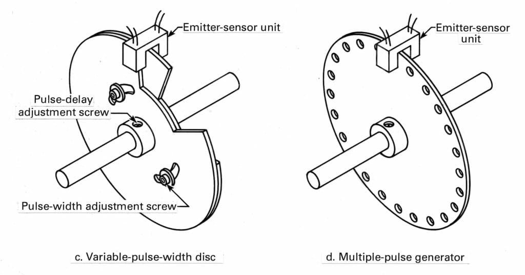
Often a signal pulse is required at the precise instant a shaft passes a certain angle of rotation as, for example, when the shaft is the basis for timing functions. Several optical methods are used to derive such sync signals. The simplest way is to straddle a shaft-mounted perforated or notched disc or a gear with an emitter-detector assembly. Sync pulses from discs and gears can be changed with respect to shaft position by mechanical adjustment. If pulse duration must be adjustable as well, both adjustments may be implemented by using two notched discs. If it is not feasible to make these adjustments mechanically, a more economical solution may be the use of two one-shot multivibrators.

Encoding Shaft Position
Absolute shaft position can be derived optically by disc encoders, which can be either standard or custom-made devices. The code need not be straight binary. In fact, special codes such as the Gray Code are usually used to eliminate ambiguity at points where the values change. In the Gray Code, only a single bit changes from one encoded angle to the next. Shaft-position encoders need not be high-precision devices in most applications: five bits are enough for unique encoding of each 11.25 deg of rotation, and nine bits generate a code for each 0.7 degree.
The encoder disc shown here requires an emitter-detector pair for each coded circle. The outputs of these pairs can be connected for parallel entry of angular position data directly into a computer or microprocessor. Special discs can be designed for operations not requiring logic processing. For example, the disc can contain switching patterns to replace multiple switch-actuating cams on a rotating shaft.

Measuring Speed
A reflective strip attached to any rotating or reciprocating surface can provide accurate speed data through the same concept used for generating shaft pulses. Again, the sensor contains a light emitter and detector. With a reflective strip on a rotating shaft, the output of the phototransistor is one pulse per revolution. (If the shaft is reflective, a dull black strip is used.) When the READ push button is pressed, the binary divider produces a gate signal derived from an oscillator. During the gate period, pulses from the detector accumulate in a decade counter whose value is displayed. At the end of the gate period the input is disabled.
Measuring Angles
A pair of polarizing filters can be used to derive an analog signal representing angular position. As one filter is rotated, light transmission through the filter pair varies sinusoidally. Two complete light/dark cycles occur in 360 deg of rotation. Although nonlinear, the transfer function of this sensor can be defined and used either for measurement or for feedback in a closed-loop servo system.
Sensing Linear Motion
In this technique, output pulses are produced by relative linear motion between an emitter-detector assembly and a transparent substrate containing dark bars. This principle is used frequently for high-resolution linear positioning as, for example, in computer disc drives and printers. To keep track of the absolute location of the moving part, a counter is started from zero to correspond with a reference position on the strip and then incremented or decremented as a function of relative motion and an independently derived direction signal. (Direction sense can be derived from the polarity of the voltage energizing a dc drive motor, for example.) Many matrix printers use the pulse signals to trigger the print hammers. In this application, the strip is fixed to the machine frame and the emitter-detector pair is attached to the moving print head.

Eliminating Contacts from Switches
Optoelectronic devices lend themselves well to a variety of general switching applications because they are fast, don’t arc, and have zero hysteresis. Although hysteresis sometimes can be put to good use, in operations such as cam-following it can needlessly complicate cam design.
Optical devices are also used to eliminate all mechanical coupling between a door and its interlock. A large number of emitter-coupler pairs can be scattered about a machine in which all doors and access panels must be in a predefined condition before an operation can start.
Weaving an Area Interlock
If a dangerous process or machine must be stopped when a person strays within a defined boundary, a single laser and a number of mirrors can be arranged to provide an invisible “net” around the restricted area. If the beam is interrupted at any point, the logic can take appropriate action.The laser can be an inexpensive 1-mW helium-neon unit, available for about $150. A total path length of several hundred feet is not unreasonable, since beam divergence is less than 1 milliradian.

Identifying Pallets
Optical methods can be used to identify pallets on conveyor systems. Typically, the pallets pass a checkpoint that reads pallet codes for routing or for loading purposes. If the environment is not excessively dirty, an optical code-reading scheme can be used. One simple method employs a 35-mm slide encoded with the binary code number and a row of synchronization bars. The slide is mounted on the pallet so that it activates sensors as the pallet passes a read station. Sync bars mark bit positions, and the data is clocked into a shift register which stores the code number. (Ten code-bit positions can generate 1,024 different codes.)
Transmitting Reliable Data
Optical couplers provide a simple means to eliminate electrical noise that otherwise could be transmitted from sensors to logic circuits through a common ground reference. Even the ground-loop resistance between two relatively “quiet” logic systems can produce unreliable data if there is no isolated current loop as an interconnection. Currently available optocouplers provide over 1,000 V of isolation.

Synchronizing Logic with the Power Line
Ac power-line frequency is often used to provide timing signals in systems ranging from digital-clocks and zero-crossing Triac controls to machine controllers. Normally, a dedicated transformer winding provides the line-synchronized, 60-Hz signal. However, there is a simpler method that provides a logic-compatible square-wave signal in addition to line-frequency synchronization. A miniature neon bulb ionizes 120 times per second when connected through a current-limiting series resistor to the ac line. Generating the timing signal simply involves optically coupling a phototransistor to the bulb and dividing its output by two with a flip-flop. The output is a 60-Hz square wave.
Monitoring Indicator Lamps
An unlit indicator lamp on a control panel means one of two things: either the lamp circuit is not activated or the bulb is burnt out. This ambiguity gives false information and can also be dangerous. One way to prevent this condition is to use a phototransistor to monitor bulb operation. In this circuit, the control logic is inhibited if the signal from the phototransistor fails to follow the signal to the lamp driver.
Interfacing Optoelectronic Devices
In the applications described in this article, with the possible exception of the analog sensor, the optocouplers can be connected to TTL logic devices. However, several requirements must be met. For example, the diagram shows a logic-controlled LED and a photodetector used for data transmission. To prevent the LED from burning out, a current-limiting resistor must be connected in series. To choose the resistance value, subtract the voltage drop of the LED (about 1.5 V) from the total voltage impressed across it. Divide this figure by the required current, which depends upon the LED type and the brightness needed. (Current requirements normally fall between 10 and 30 mA.) In the diagram, the LED is grounded or connected to a near-zero voltage when a driving signal is applied to the TTL open-collector inverter. However, the low end of the diode is hard-wired to ground or near-zero voltage (LED is always on) when beam interruption is used.
The phototransistor can be directly connected to the control logic, if it is nearby. More often than not, however, the logic is located remotely, thus requiring a length of wire between it and the receiving device. If the environment is electrically noisy, the wire should be shielded and the receiving device should be a Schmitt trigger. This device is an excellent noise buffer since it has a large hysteresis loop. To satisfy the low-voltage input requirement, it may be necessary to supply a slightly negative voltage to the collector of the remote phototransistor. This combination of techniques usually produces a safe noise margin. But if the margin is not adequate, the current-loop technique can be used.
You must be logged in to post a comment.