
Crossed Signals logic puzzle – Computers and Electronics
This was just a little quickie that challenged readers to make a logic diagram with an unusual constraint… no lines could cross!
by Steven K. Roberts
Computers & Electronics
March, 1983
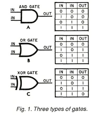
One of the basic elements of computer circuitry and digital logic is the gate. There are three fundamental types of gates:
- AND gate, whose output is a 1 if and only if both inputs are 1
- OR gate (also known as an Inclusive OR), whose output is a 1 if either or both inputs are 1
- XOR (Exclusive OR) gate, whose output is a 1 if either, but not both, inputs are 1
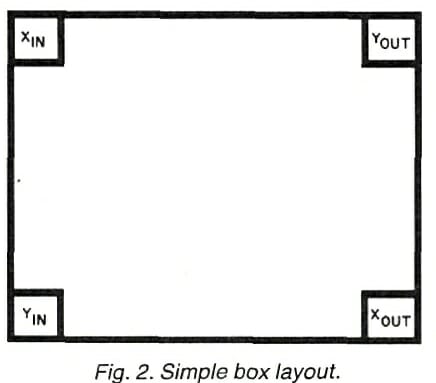
To learn how to use these logic elements in designing a circuit, try the following quiz. Starting with the simple box layout in Fig. 2, connect Xin to Xout and Yin to Yout with logic gates so that the effect will be the same as if two simple wires had been used to make the connections. That is, a logic 1 applied to Xin should appear at Xout and a logic 1 at Yin should appear at Yout. The problem would be trivial except for one small consideration: no lines may cross on the diagram! You may use as many gates as you like—of any type.
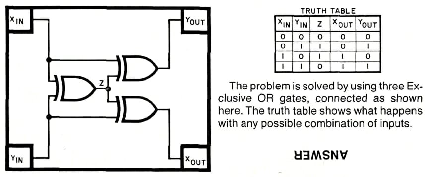
It’s a fun mental exercise to play with this for a bit before looking at the answer, so I’ve made it a partial thumbnail… the magazine just put it on the same page, upside-down, which made it much too easy! Click this tiny box to see the answer:

You must be logged in to post a comment.