
Sailboat Desk Fabrication
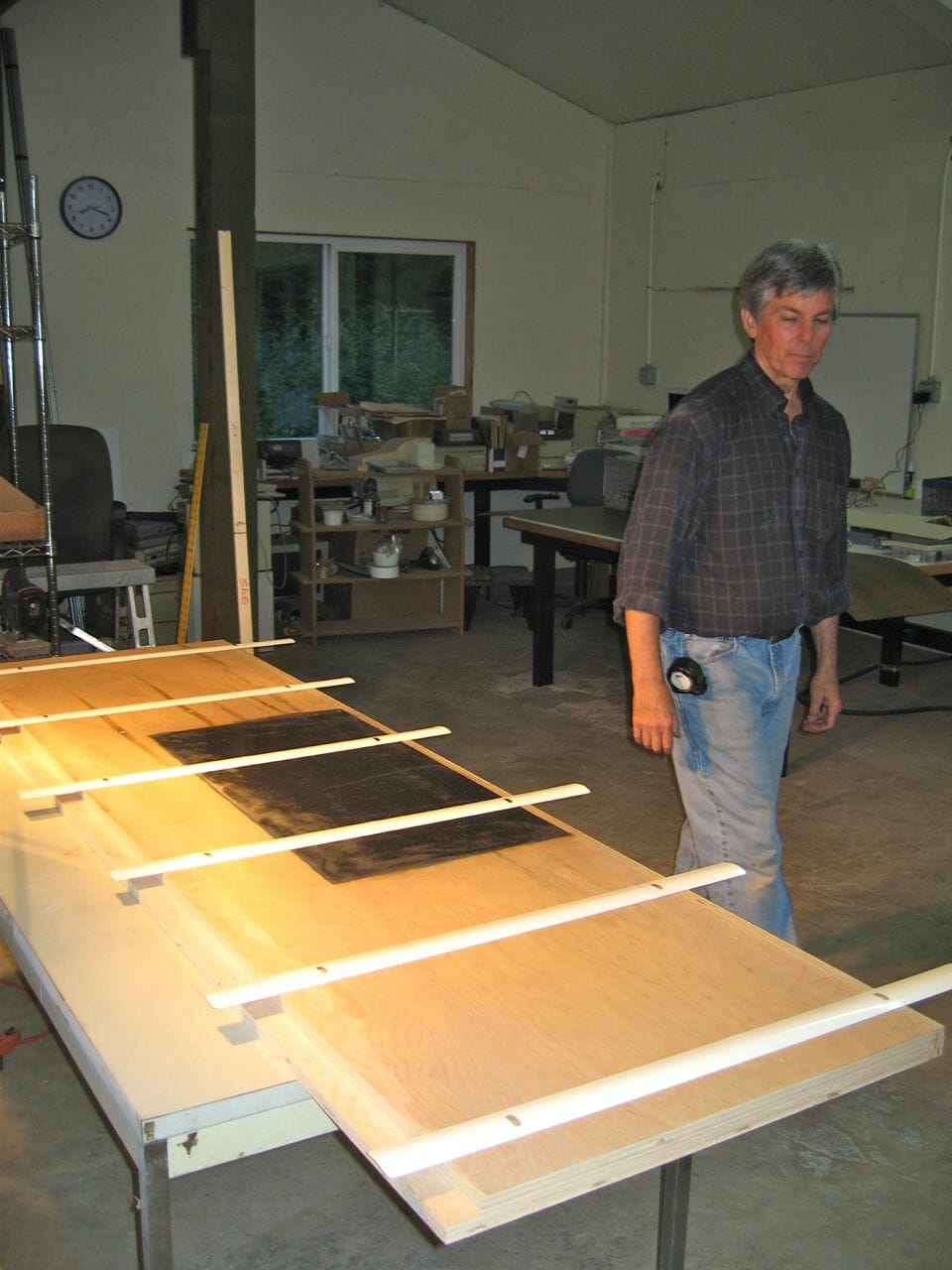
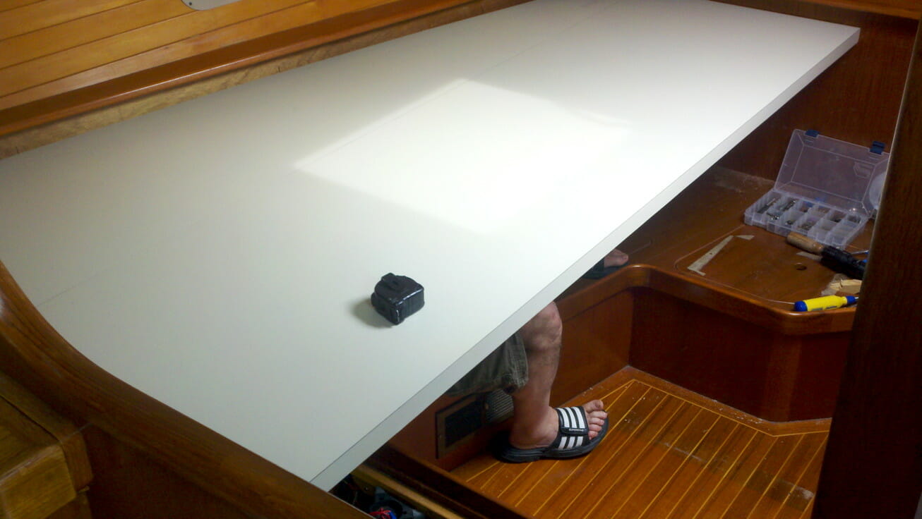
This is a major step forward; I finally have a lab desktop aboard Nomadness. For about a year, my work surface has been but a crude plywood visualization model in place of the original cramped dinette… saggy, rough, and not dimensionally accurate enough to use as a basis for any subsequent design. But thanks to the creative efforts of Fred Westergaard, who is turning my old Microship lab into an exquisite wood shop, the substrate of the console is now complete.
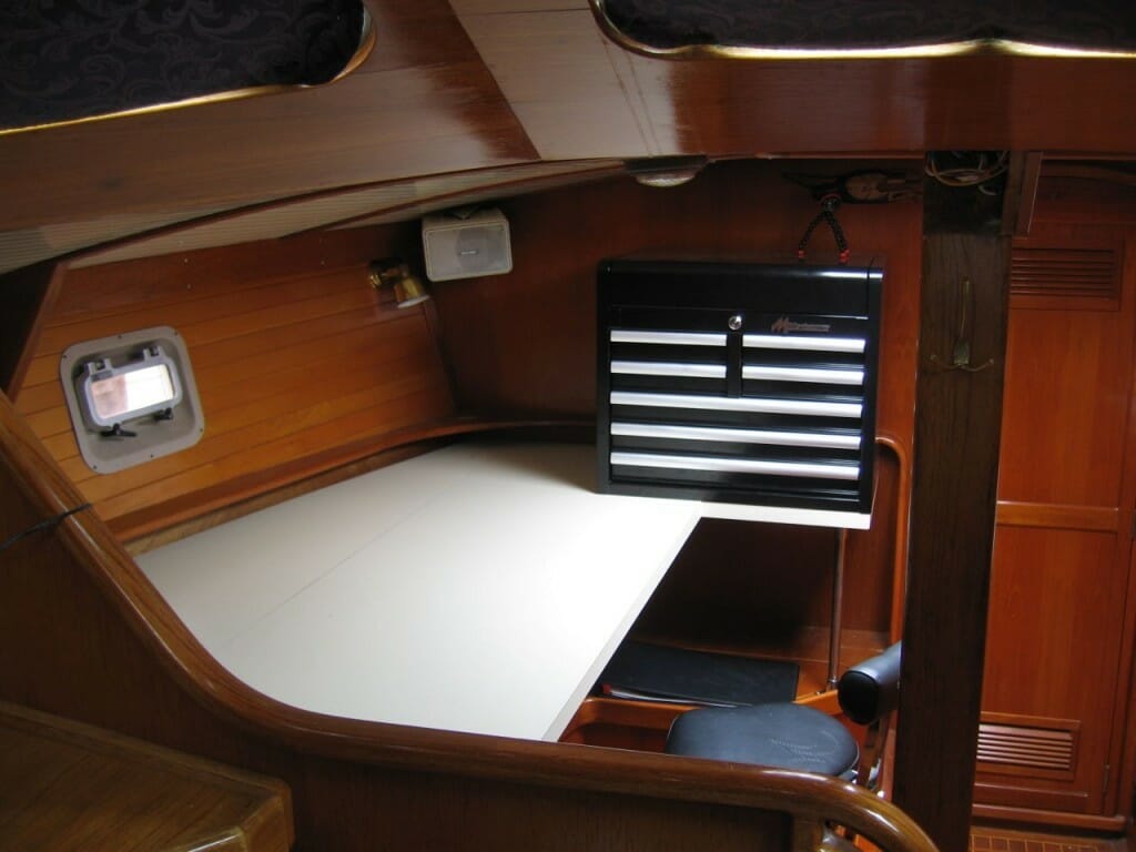
The photo above shows the current space, and this article is about the fabrication of the laminated structure… there are a few non-obvious details, and it was quite educational. Features include assembly in two parts to allow passage through the companionway, an underlay of 16-gauge steel in the central region to allow magnetic fixturing, 1.5-inch thickness and a central stainless post to prevent sagging, a cable-passage corner on the left rear corner, and tool chest integration. From this will flow the wrap-around console of three tall rack enclosures, with a lower one in the foreground to prevent turning the lab into a cave.
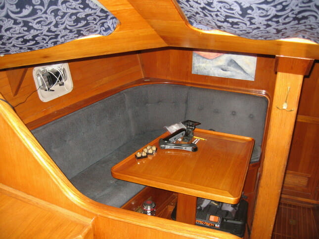
Just for a quick background, this photo shows the space as it used to be. I was never able to get comfortable at that table, pretty as it was, and it was thus a repository of clutter most of the time. Access to stowage areas under the cushions has not been sacrificed.
Lab Desk Fabrication
To help other folks with similar projects, I’d like to show you in detail how this was done. It’s actually a cool process, and it was most educational to play apprentice with someone who possesses skills so different from mine.
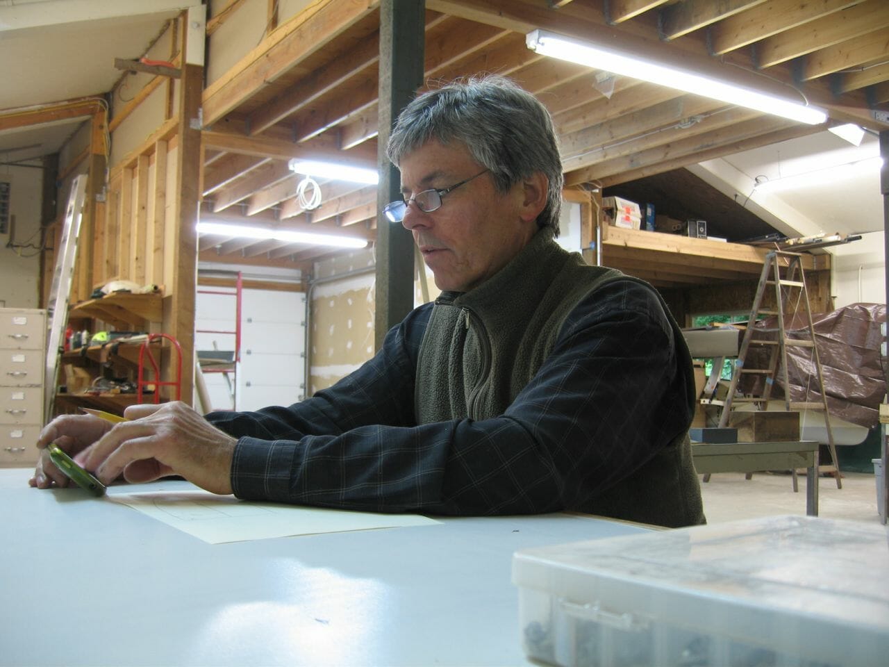
Fred Westergaard, as I mentioned above, is the fellow who bought my property on Camano Island. He is turning it into something wonderful; I had let it languish, exhausted by projects that didn’t reach escape velocity and frustrated by the impossibility of working on a distant sailboat while stuck in the middle of a forest. But he is infusing the place with a whole new energy, not only giving the house and grounds a much-needed refresh but turning the old Microship lab into the ultimate shop he’s been wanting for years. All that added an interesting twist to the process of working with him on this project… showing up at my old place to assist. Can you imagine, after spending 13 years there (not to mention being the one who built the 3000 square-foot shop back in 1998)?

The first step was, of course, to plan it out, forcing me to answer the “how high? how deep?” questions with something more precise than vague hand-waving. This is where my tired old plywood model shown here paid off, so before long we had some working dimensions… constrained by the need to bring it aboard via a companionway that can only pass items about 32” wide.
The design goals had to be clearly stated as well: a robust tabletop that will not sag under the load of consoles or human weight, solidly attached to bulkheads and supported in the middle, laminated to provide a bright work surface with a steel zone in the center for the magnets, and split to permit installation without compromising strength. We also wanted to include a “wing” at the right to support a 26” tool cabinet, and of course (it goes without saying), it had to be beautiful… unlike the crude mockup in the photo.
(All along, I’ve been wanting this to have a lifting lid that reveals a full-size digital piano, but our initial brainstorm session revealed that to be unrealistically complex… and it would have imposed constraints on future keyboard changes. So the MIDI controller will slip into a compartment under the desk and pull out as needed.)
OK, let’s build this thing!
Getting started
As mentioned, the first step was to establish dimensions; this design should scale to many different boats with appropriate customization. In the rough sketch below (not at all to scale), we can see the encapsulation of some key design requirements.
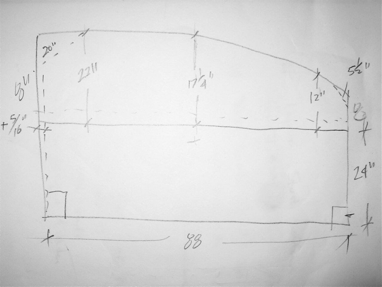
We were fortunate to have almost parallel bulkheads, which are the lines at the left and right ends of the sketch (marked by right-angles in the lower corners). There are 88 inches between these surfaces, but it had to be shortened a bit to allow installation without interference with a little rail that bounded the tops of the original cushions. I wanted to keep this for various reasons, not the least of which was minimizing surgery in case some future owner wants to restore the original configuration.
The horizontal line in the middle (with faint dotted line lost in flash glare just above) defines the split that allows this to fit through the companionway. Obviously, strength would be compromised if there were just two surfaces butted together, so we took advantage of the two laminated 3/4” plywood pieces to create a substantial ledge (1-1/2”) extending from the underside of the front piece to support the rear one along the entire joint (screwed in place).
Finally, measurements from this reference line to the curved outer hull of the boat give us the shape of the distal piece, which also needs to have a vaguely-defined corner lopped off at the left rear corner to allow easy cable passage between the future console systems and the rest of the ship.
Gluing the layers
We discussed the type of plywood, judging the obvious “marine ply” overkill at twice the price because it’s well-encapsulated. Time will tell if that was a wise decision, but we chose a nice shop maple at $61/sheet from Dunn, a local lumber yard. I believe this is a birch core with maple veneer, and was very pleased with its flatness, smooth surfaces for gluing, and minimal voids. (Note from 2017: I wish we had done this with the lab desk in Datawake; a local woodworker used some awful ACX, and it’s lumpy and saggy.)
Here, Fred is gluing two layers together… we wanted an overall 1-1/2” thickness to keep it from sagging, and this has turned out to be an excellent approach (it’s rock solid). The adhesive is the excellent Titebond III (about $18/quart on Amazon). He swears by this stuff, and I see why; playing with a cut-off scrap later, I found the bond stronger than the ply itself. In a later photo, you’ll be able to see some of the clamping that was applied, but we really had no problems. I did ask about islands in the glue pattern without oxygen, but that’s only an issue with non-permeable surfaces. Even the fine-grain maple veneer has enough internal gas space to keep any region from staying wet for long.
Steel Inlay
I forget who first suggested this, but early in the process I decided to add a layer of steel in the central work area of the desktop. This will let me embed magnets into various objects that need to stay put (though one fellow on Facebook pointed out that this could detune RF circuits under calibration… worth remembering). In a bouncing/tilting thing like a boat, I like the idea of keeping a few items stable… including lights, third-hand, random fixtures, and a detachable “fiddle” along the front edge.
A good dimensional reality-check is this online steel thickness calculator from my favorite magnet vendor.
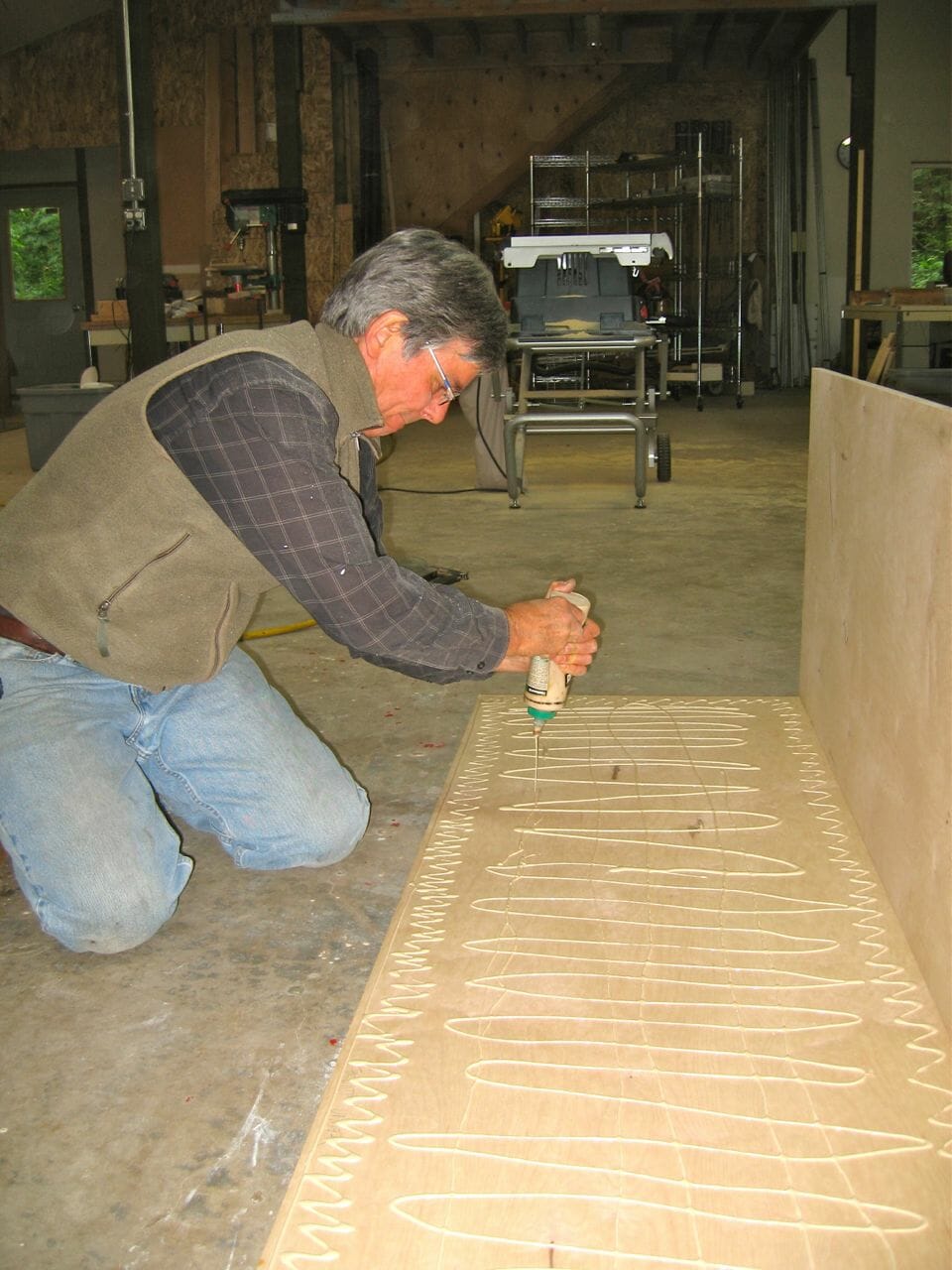
The metal is a 16 x 32 inch piece of 16-gauge hot-rolled steel, $36 from Teeter’s in Seattle, and you can see it resting on the surface above where Fred is using the pneumatic nailer to provide a bit more clamping pressure for the fresh glue joint. (Both sides were roughed up with 36-grit sandpaper to improve adhesion.)

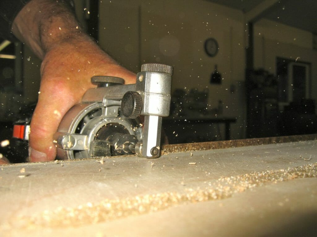
He then carved away as much as possible using the router, keeping strips intact as a reference plane… then chiseled those away to create a tight nest for the steel. In the photo below, he is clearly pleased with the results, with the metal nicely inset while surrounding clamps keep pressure on the glue joint.
It was time to break out the contact cement, which would also be used to do the laminate covering the whole surface. As you can see in, it’s a green can, not the familiar red one; this is Dap’s “nonflammable” version instead of the “original.” The difference is in the chemistry, with the green stuff being latex-based… much easier to be around than the original brain-cell-destroying explosive VOC-outgassing stuff.
Interestingly, however, most of the Amazon reviewers really hate it, and only some of them were clearly doing it wrong. This may suggest some batch variability, which is concerning, but I discussed it with Fred (who used the original formulation professionally for years), and he said the rules for this version are quite different. With the original contact cement, there was a narrow window between too wet and too dry (though you could easily refresh a layer by adding more, at the cost of additional thickness). One test was laying a piece of paper on the prepared surface; if it stuck, it was too wet; if it fell off, it was too dry. But if you apply that same rule to the latex stuff, it will always be too wet… so some experienced folks give it one test and discard it. It must be more dry before bonding.
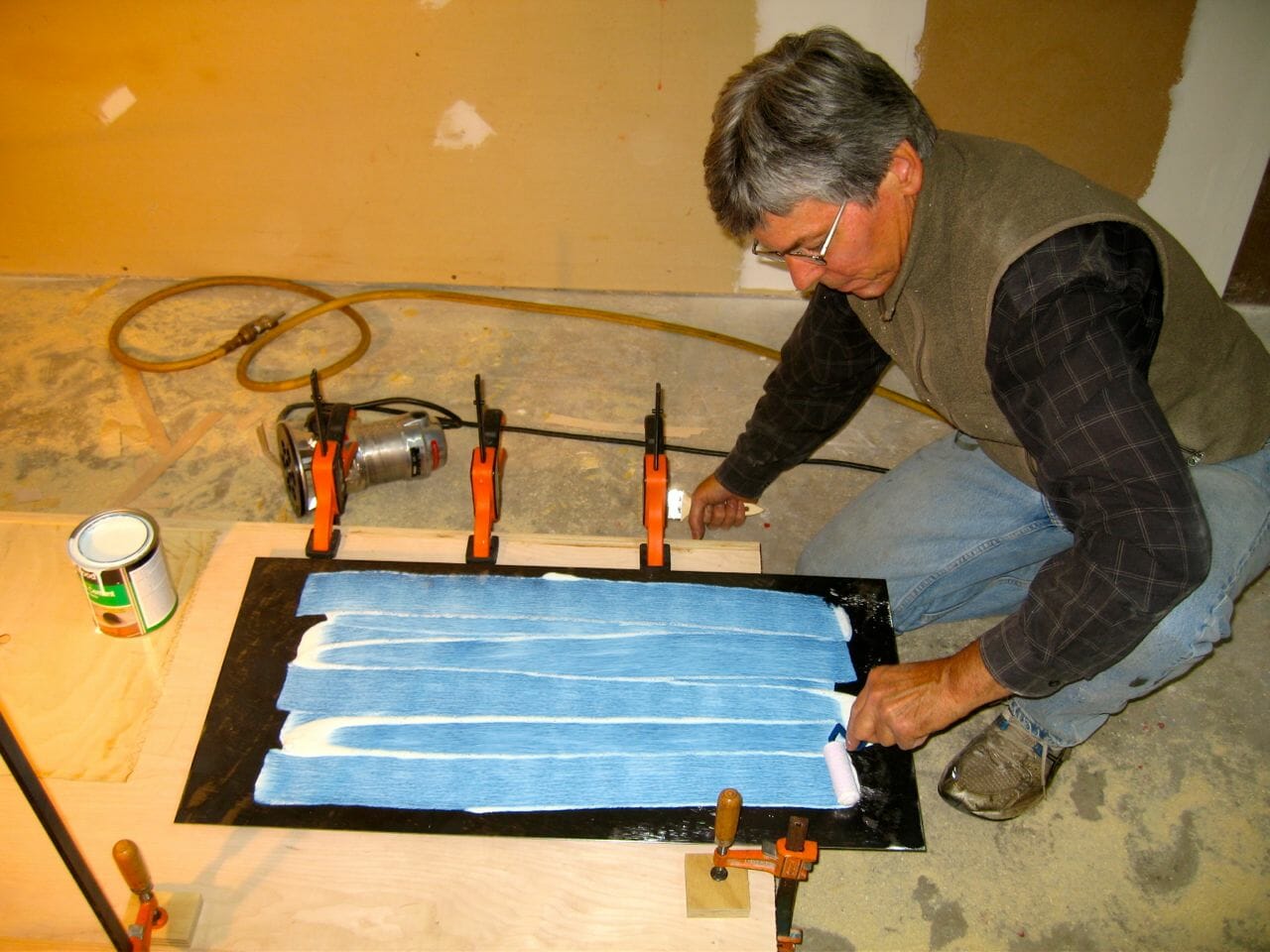
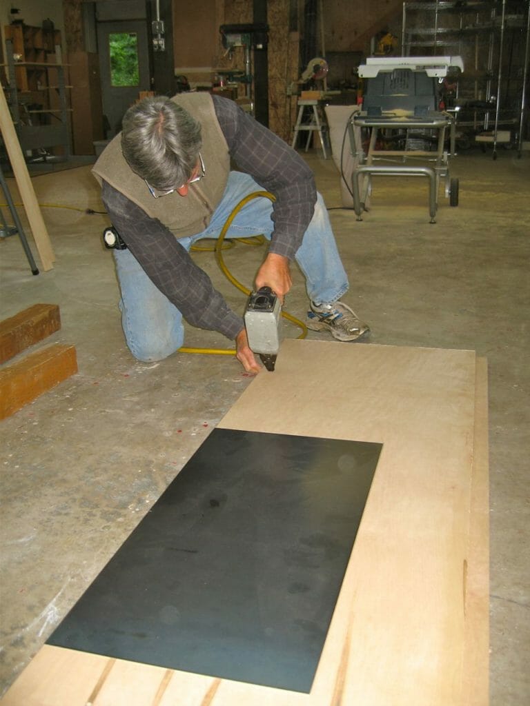
In this photo, Fred is gooping up the steel prior to dropping it into its nest, and in the next photo you can see it solidly in place as he takes the belt sander over the whole surface to prepare it for the laminate. We did have one tricky corner (right front) where the steel didn’t want to lay all the way down, perhaps due to a stray wood chip coupled with a little bit of pre-bend. We fixed that with a countersunk screw, which cinched it down nicely.
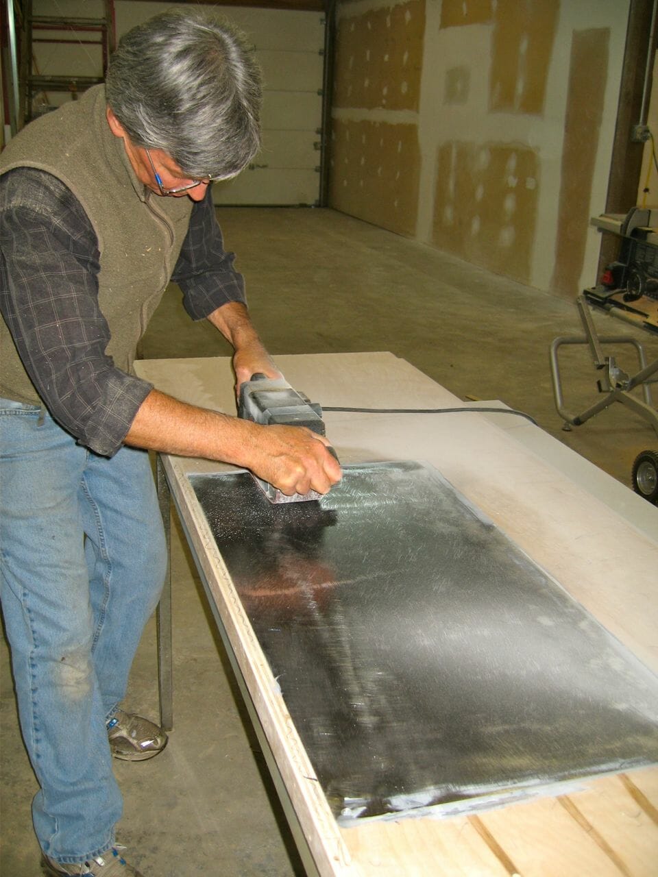
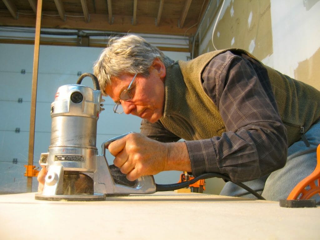
The sanding step is critical, since any little high spot can create a pesky bubble in the laminate, so that got very careful attention here. One of Fred’s tricks was to glide his hand over the preassembled surface, then make waggly pencil marks on any area that needs to be finished further. Those act as an indicator during sanding, so it’s easy to tell when you’ve covered the area (and, significantly, when you’re in danger of going too far).
Once this was done, it was time to do our surface with WilsonArt D30-60 natural almond (which matches the material in the boat’s headliner to give the workspace a nicely integrated look). Alas, the first 4×8 piece arrived damaged, with a big blowout right in the middle, so we paused to re-order and continue another day!
Lamination

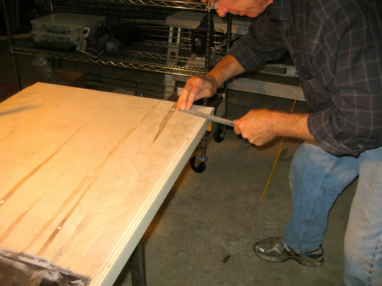
Once the new sheet arrived, we dove back in… beginning with cutting out the pieces. This is basically just making a deep groove along a straight-edge with a carbide scoring tool and then bending the whole thing until it snaps (kind of terrifying, after seeing the damaged sheet, but it went perfectly). The first part to be glued was the front edge, since we would want the top surface to overlay that before trimming.
Through all this, Fred kept up a running commentary on the process, and that’s one of the things I most enjoy about working with experienced people on projects. There’s nothing like a good learning curve….
(Throughout this discussion, I’m leaving out the redundant details of doing the same thing on both segments of the desktop… that would just be confusing.)
After we applied the edge, an easy job with nothing floppy to handle and no critical alignment issues, Fred applied local pressure with rubber and steel rollers, then zipped off the excess with his vintage 1977 Black & Decker laminate trimmer and cleaned it up with a sharp file.
And then it was time for the big piece… about which I was having grim visions involving uncontrollable sag, premature adhesion, and gunky messes. But a few months ago, while making one of countless pickup-truck loads between my old mountain of clutter and the temporary digs in La Conner, Fred had enthusiastically accepted my offer of a batch of old steel Venetian blind slats that I had been dragging around in the category of “long stuff” for decades. He said they are the best solution for keeping laminate under control while cementing, since they can keep the piece just above the surface and then be pulled out in succession without mangling the glue.
I was about to see him actually execute this magic trick…
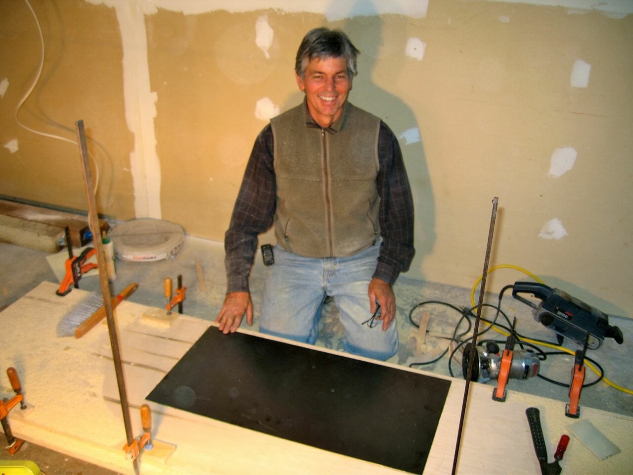
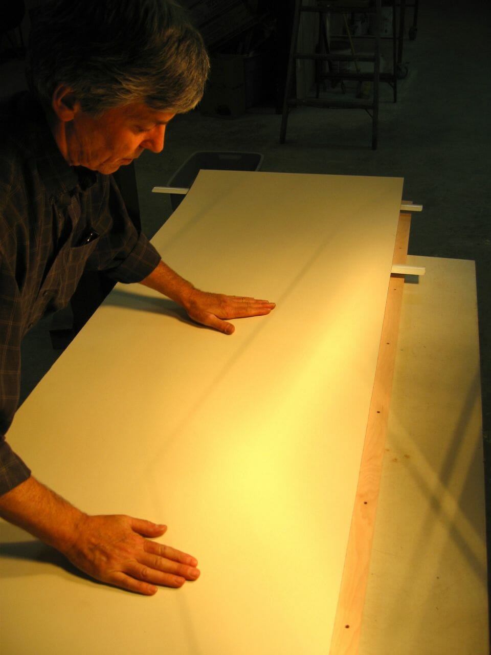
It was actually much less dramatic than I expected. After we flipped the cut piece upside-down and buttered both it and the substrate with contact cement, we allowed it to nearly dry (still slightly rubbery) and then went for it. The blinds were evenly spaced on the plywood surface, and while keeping a slight bow to prevent sagging, we laid the laminate on top. This gave us lots of opportunity to make sure it was aligned properly, and then, starting at the center, we simply pulled out the supporting strips (“like nuclear reactor control rods,” I observed).
Once this was firmly rolled down and the edges trimmed (and the mating part completed identically), we were basically done with the shop phase of the project. We did to a test fitting on the floor, including the row of screws at the junction ledge, then started plotting the actual installation in the boat.
This would involve three separate support structures: a robust 2×2 angle of .25” aluminum on each bulkhead, three brackets of plywood along the rear edge where it meets the hull side, and a single post of 1” stainless tubing in the middle.
Preliminary tests in the spacious setting of the shop proved that sag was not likely to be a problem… this is actually more of an issue than it would be if it was only doing tabletop duty, since it is also the substrate of the wrap-around console and we really do want it flat. It is, I am happy to observe, flat.
Installation
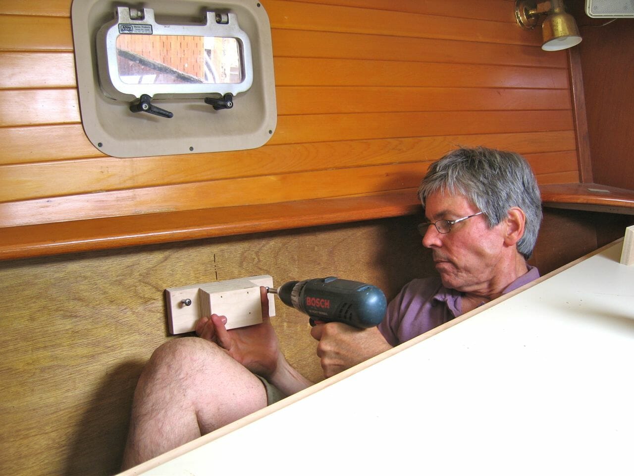
Here is a collection of photos from installation day… a little fine-tuning, wrestling the parts into place for a reality check, bolting aluminum angle to bulkheads, projecting the resulting plane to the curvy hull, mounting the rear supports after cutting them to the right angle on the table saw, and the beauty of it gradually taking shape. All this is installation-specific, relevant only to my boat, and your details will differ… so I won’t elaborate.
You can see both side and rear supports, as well as the seam joining the two desktop sections. That is also the lopped-off corner I mentioned, which will provide clearance for cables into the boat’s wiring harness.

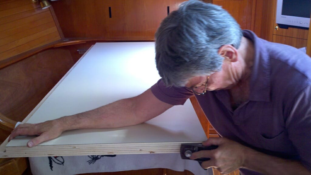


Desktop installation Nomadness was as fiddly as one might expect, given the fact that nothing on a boat is perfectly square or level… we cheated it slightly to the left to match that visible bulkhead, with the slight angular error to be hidden by the tool cabinet on the right. It went in beautifully, dead-flat and stable, and immediately improved the sense of efficient workspace in this constrained space. One last task remained… integrating a tool cabinet “wing” on the right side, against the forward bulkhead.
A place for tools
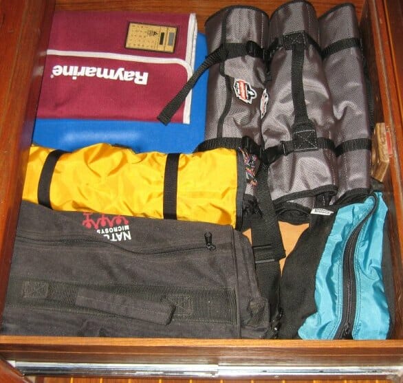
When I first bought this boat, I optimistically Tetrised all my tools into a perfectly space-efficient little package that nestled into a drawer located under the seat of what is now the lab region. This was completely unrealistic, and I’m not sure it was ever as neat as it was in the photo accompanying an old article about favorite tools. This just doesn’t work… roll-ups are a pain and they never get put away. An integrated tool cabinet was thus a key part of this lab desk specification.
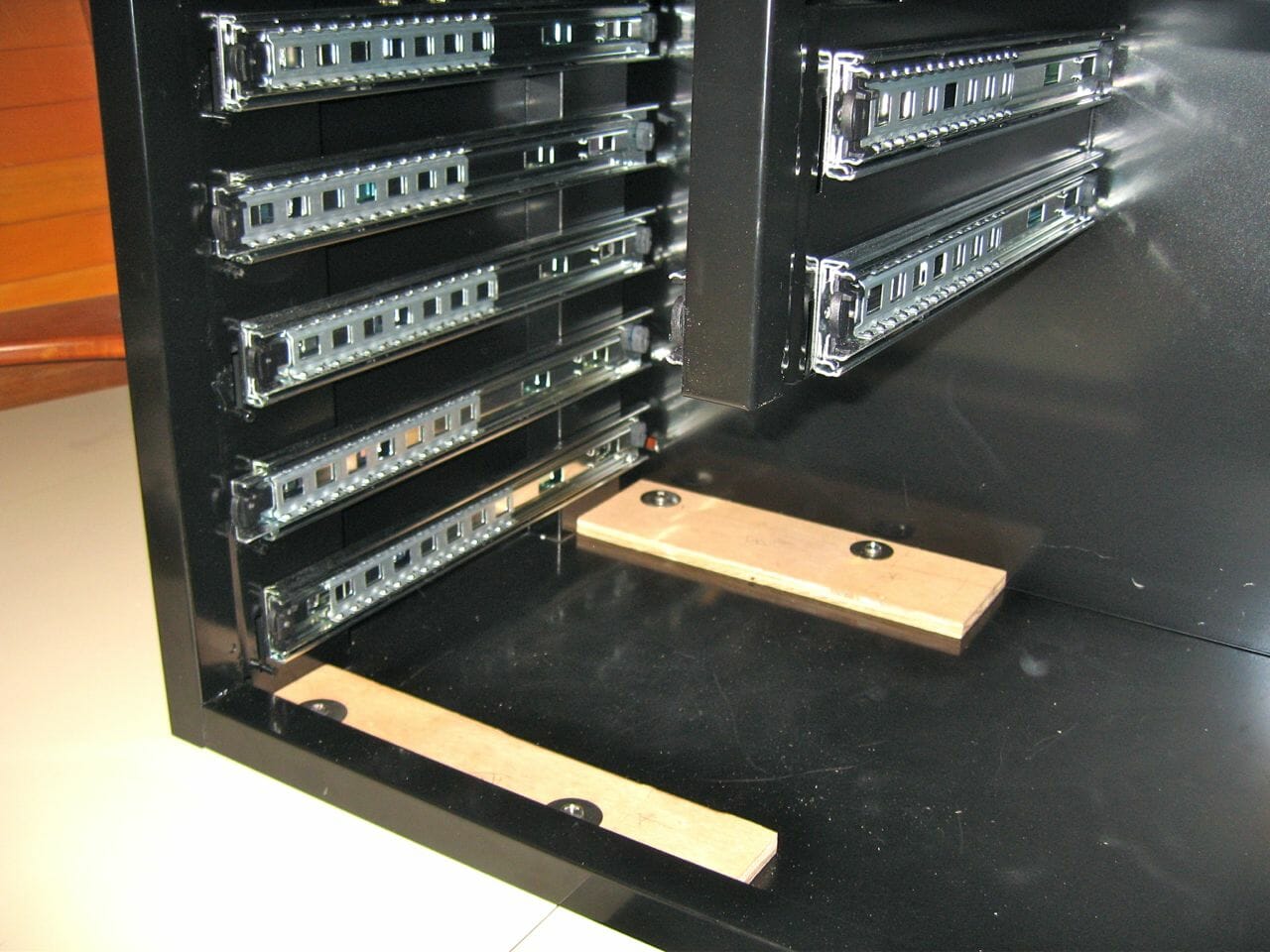
It’s hard to find a good tool box these days without spending big bucks (Kennedy, Snap-On), but this one isn’t bad… with good drawer detents and a solid lock. There is exposed steel that will need Corrosion-X or Boeshield, but for $250 at Sears, I’ll take it over their Griplatch model that felt like a beer can. We added a non-structural wing to the desktop with a bulkhead bracket and stainless support post, then fastened the cabinet down and removed the useless side handles.
And I love it… being able to put things away means I’m more likely to find them when I need them, and the location is perfect. The left edge of the tool chest is the beginning of the wrap-around console space, which I hope to be writing about Real Soon Now…

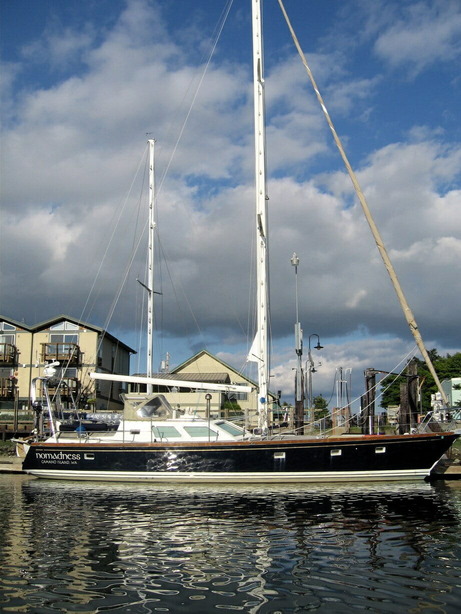
Nomadness moored in front of the previous development facilities in La Conner
You must be logged in to post a comment.