This was a quick little hack… way back in the day, a good and cheap tool for programming EPROMs in an S-100 bus computer was a board called the Bytesaver (by Cromemco). The only catch was that for every cycle, you had to shut the computer down and pull out the board. In a production development environment, this was crazy… so I made this little gadget and wrote an article. Decades later, the dang thing is still following me around… so I added two photos of the dusty old relic.
by Steven K. Roberts Kilobaud Microcomputing October, 1979
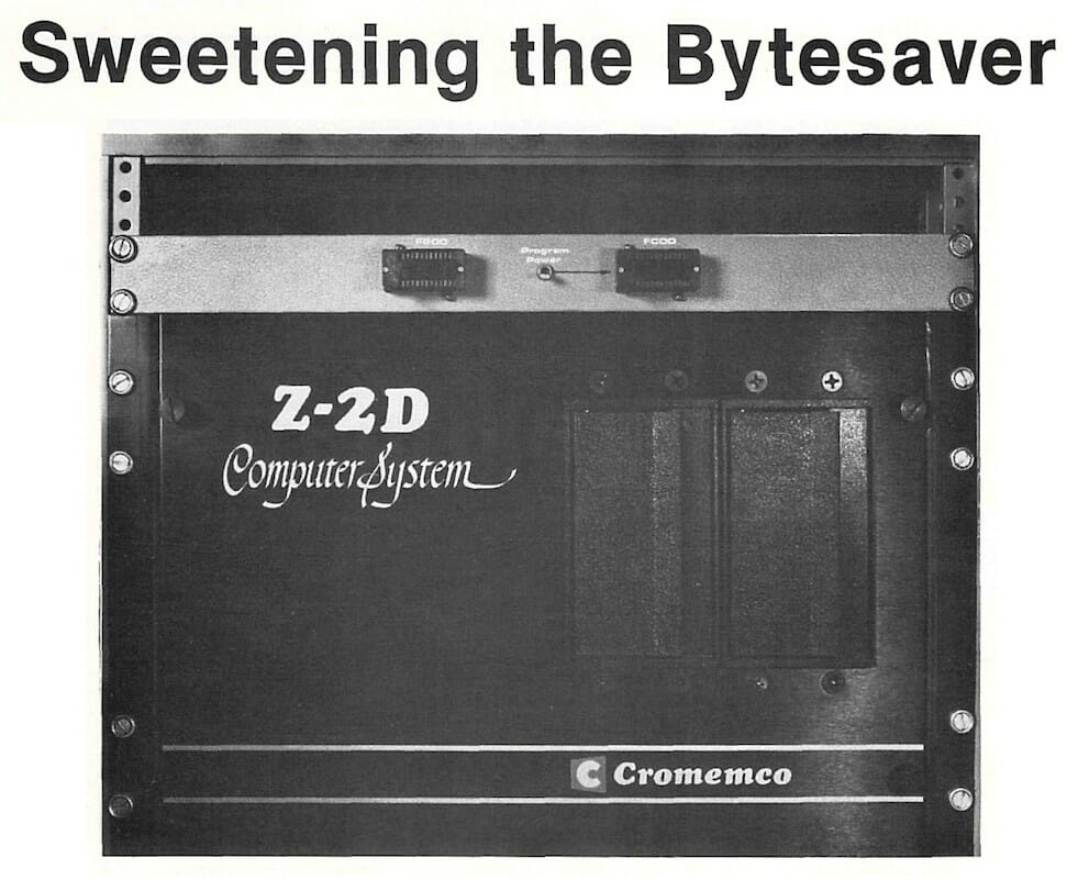
The Cromemco Bytesaver is a useful addition to the circuit board repertoire of the owner of an S-100 bus system.
Useful as both an 8K PROM card (eight 2708s) and as a programmer for same, it is a bargain at a kit price of $145. Its utility can be even further increased, however, by implementation of the technique shown here.
Remote Programming Panel
Perhaps the single most troublesome aspect of programming EROMs with the Bytesaver in its standard form is that it is necessary to power down the system, unplug the board and cycle the IC sockets during each iteration of the program/debug sequence. This can wear down both the connectors involved and the nerves of the user; in my case it led to the addition of a front-panel programming station connected to the Bytesaver by a ribbon cable.
The result is shown in Photo 1. The sockets chosen were the Tex-tool units (224-3344 with receptacles)… costly parts but the best around for the heavy-duty requirements of EPROM programming. Standard 24-pin sockets would work — for a while. The switch between the sockets replaces the program power switch on the Bytesaver card.
Operation
Operation of the unit is simple: A 2708 is inserted in the socket on the right (addressed at FC00); the switch is turned on; and the DEBUG, ZM1 or BYTEMOVER software is directed to program the chip. After programming, the switch is turned off. The other socket position is provided on the panel to simplify copying data from one EROM to another; but this can be a two-stage affair via system RAM if you wish to keep socket costs to a minimum (the bill from the Tex-tool distributor was $34).
Modification
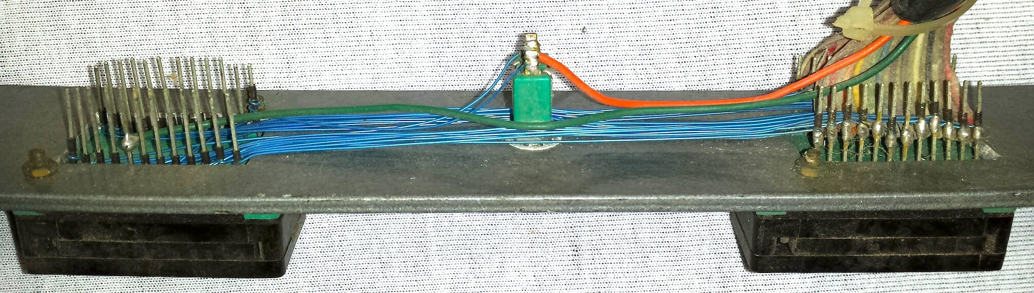
Photo 2 shows the details of the modification. Since the only difference between the wiring of the eight EPROM sockets on the card lies in the source of the chip select signal, two front-panel sockets may be supported with a 24-line cable, plus one wire for the second select (pin 20).
A second additional wire is added to carry the status of the program power switch. To allow separation of the panel from the board and to simplify installation, the cable should be terminated in a 24-pin DIP header. The two troublesome piggyback lines, in order to be pluggable as well, terminate in a kludge comprising a bisected 14-pin header and a DIP socket glued sideways onto the EPROM socket adjacent to the first one. The other six sockets on the Bytesaver are unaffected and may be used as originally intended.
The schematic in Fig. 1 shows how straightforward the modification is: Wiring of the circuit involves merely the extension of existing signals. The only precaution to be observed, aside from the avoidance of error, is keeping cable length at a minimum. Crosstalk in ribbon cable has a justifiably bad reputation, and there is bound to be some degradation of pulse integrity.
A recommended step in the prevention of trouble from this source is the use of low- crosstalk ribbon (available from Spectra-Strip or surplus from Optoelectronics in Florida), or better still, ribbon cable with every other line grounded. As shown in Photo 2, I used the former and have had no problems.
Plugging Chips
Questions arose during the process of making the conversion concerning the desirability of plugging in the 2708s while the socket was “hot.” My intuitive response was that such behavior was an optimal way to destroy chips, so I checked with Intel. The 2708 data sheet states that power on/off sequences should follow a rigorous procedure, with VBB (-5V) applied prior to Vcc (+ 5V) and VDD(+12V), and with VBB also the last supply shut off.
Systems Division, which routinely builds Intellec Microcomputer Development Systems with front-panel EROM programmers, ignores all that and allows unrestricted plugging and unplugging of the chips. Other programmer manufacturers seem to do the same (in fact, I could find no industrial user who followed the Intel specifications), so I concluded that the little devices are tougher than their makers suggest.
Whatever the case, the unit shown in the photographs has programmed about thirty 2708s since it arose from the bench clutter, and they all perform their function uneventfully.
Free At Last!
The modified Bytesaver brings out of the closet much of the latent usefulness in the original design. Freed from the gut-wrenching thermal cycling associated with frequent power-up/down sequences, the process of system development involving EPROMs is almost pleasant.
It is no longer a necessary chore to disassemble your rack-mounted processor in order to change a status bit in your I/O driver or to copy a program for an associate, and contact wear, both on the venerable S-100 bus and on the ill-suited TI sockets, is kept to a safe minimum. It might even be possible to screw on the cover and forget it for a while!


You must be logged in to post a comment.