
Winnebiko 2 Solar Power System
From my series in 73 Magazine, this details the power management system on the Winnebiko II. I’m so glad now that I wrote such things then, as it would be nigh-impossible to reconstruct from the sometimes sketchy documentation binders of the epoch! This one has the additional advantage of a second voice… my friend Glenn Glassner, who helped with that part of the system, weighs in and explains the design of the switching power supply. A schematic is included.
The 73 series was fun. This magazine was irreverent and not afraid to take on non-traditional topics, and I had pretty much free rein to rhapsodize at will.

by Steven K. Roberts
73 Magazine
May, 1988
From the perspective of a sandy towel on a Key West beach, there is something abstract and remote about magazine publishers and deadlines. The attitude of mañana pervades the island air like the fragrance of frangipani, rendering the daily realities of business about as substantial as stray radio waves. . . editors notwithstanding.
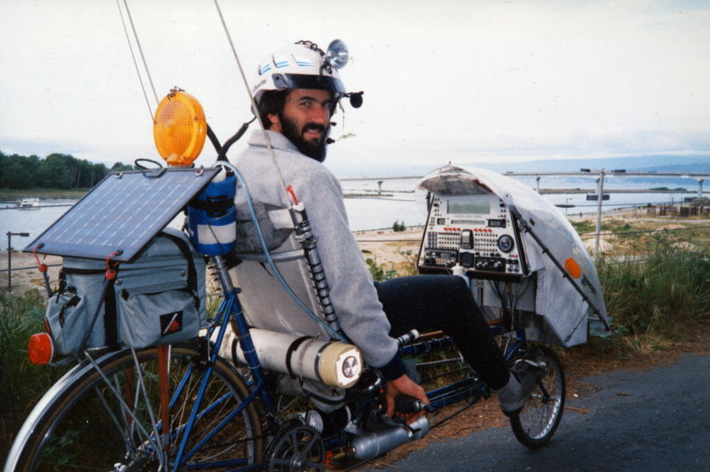
But there’s nothing at all abstract about the sunlight down here in paradise — which is a good thing for both the bikini-clad spring-break beach crowd and the power-hungry Winnebiko. Free electricity, and lots of it. keeps my systems happy, unconcerned with noisy island power lines or the grim problems of dead batteries in the wilderness.
In this, the fourth article of our series, I’d like to talk about the bike’s power-management circuitry… starting with the solar panels that take it in and ending with the switching power supplies that put it out. The whole system is designed to provide maximum independence and efficiency. The resulting ideas can be applied to a wide variety of mobile, portable, and field-day systems.
Solar Panels and Batteries
The bike carries a pair of Solarex SX-10 LITE photovoltaic modules, each weighing in at less than 2 pounds and producing a steady 650-700 mA into an associated 12-volt battery when the sun shines. These rugged 12 X 17-inch units, based on semicrystalline silicon technology and lacking the traditional heavy glass cover plates and aluminum frames, have finally rendered photovoltaic use as easy as it should be: sunshine in, two wires out, no maintenance in between. The theoretical maximum power from the pair is 20 watts, but since the panels arc mounted at different angles they can never both see full sun at the same time (at least in THIS solar system).
This is hardly a problem, however, since the bike’s loads are supported by a pair of six amp-hour lead-acid batteries, built around SAFT Gelyte packs. These replaced the original NiCd packs of my first 10,000 miles after experience demonstrated that despite a somewhat higher power-to-weight ratio, NiCds don’t like the random charge-discharge cycles of a nomadic lifestyle.
Two photovoltaic modules and two batteries… this architecture is no accident. A pair of console switches allow the former to be swapped relative to the latter — or the latter to be swapped relative to the bike’s loads. The first swap option allows a low battery to get the benefit of whichever panel happens to be receiving the most light: the second allows the computer battery to serve as a backup for the “lights and radios” battery during long night rides.
This raises an interesting issue: charge management. Ideally, this would all be controlled via A-D converters and power MOSFETs by one of the bike processors — something that was, in fact, one of my original specifications for the system software. But the catch here is that the computers are not necessarily powered up when battery charge levels are changing (keeping the bicycle-control processor on all the time would impose enough overhead to offset much of the system’s efficiency). Still, a future enhancement will allow many of the charge management decisions to be made in software when the bike is online, now that the use of lead-acids allows battery level to be measured with some repeatability.
At the moment, I use two tools to keep the batteries healthy. The first is a simple brute-force circuit associated with each, consisting of a series-check diode to prevent dark discharge into the panels and a power zener that warms up when the battery’s terminal voltage reaches end-state levels. This seems a bit crude these days, but the approach works noticeably better than my earlier active controllers that created noise and ate about 8 mA on standby.
The second charge-management tool involves what I have come to call my “wetware infosystem,” otherwise known as the human brain. A front-panel Acculex digital panel meter displays the terminal voltage of each battery, as well as the algebraic sum of all charge and load currents. After 4.5 years on the road, I have developed an intuitive sense of battery health based upon casual ongoing observation of the displayed data.
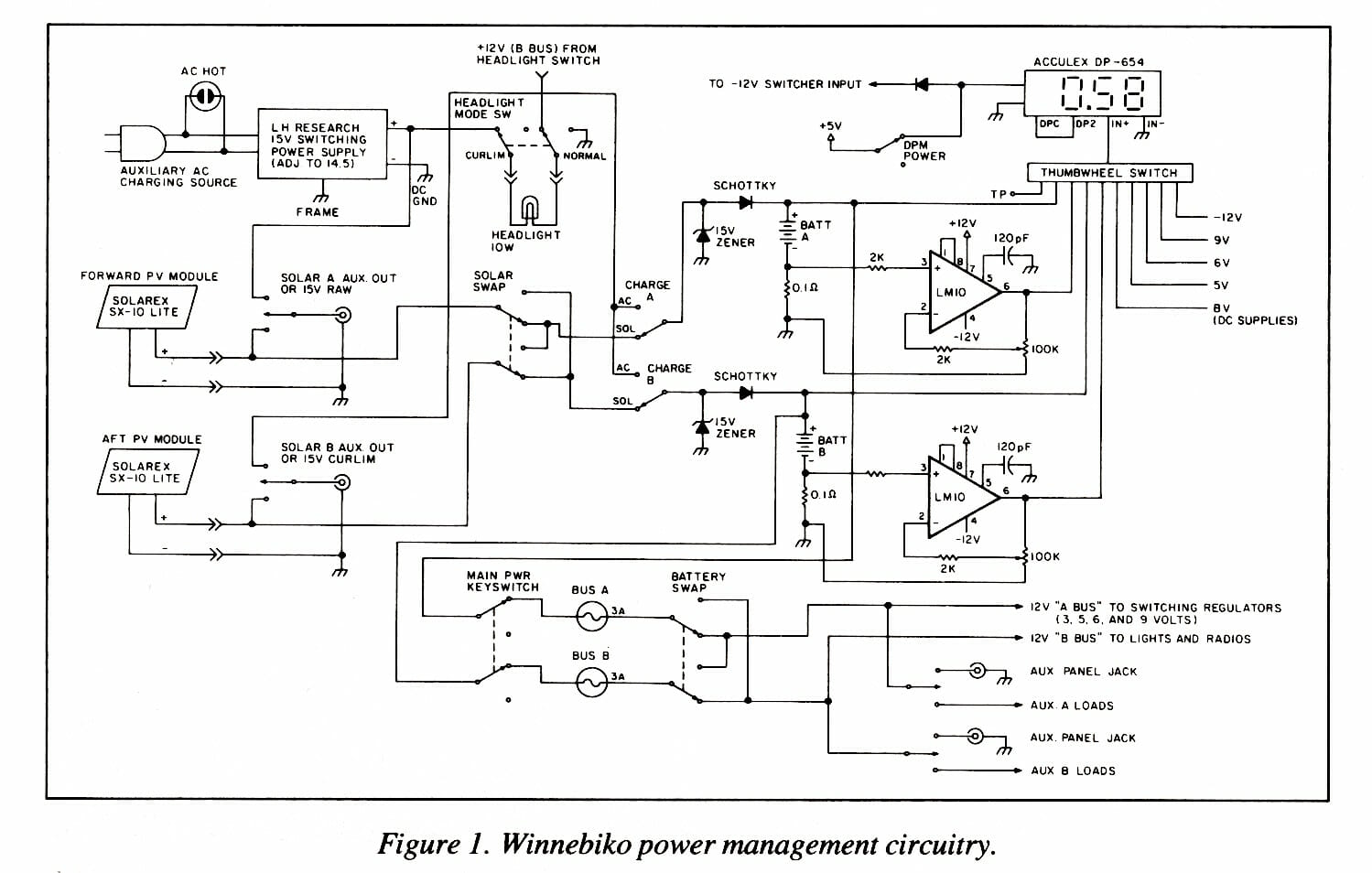
As shown in Figure 1, this information is derived by observing the voltage drop across a 0.1 ohm resistor connected in series between each battery’s negative terminal and system ground. (Doing it this way keeps op amp circuitry trivial.) This measured value, which linearly reflects battery activity, is scaled to +/- 5 volts by a micropower LM10. Then it is handed off to a thumbwheel switch that feeds any of ten diagnostic voltages to the panel meter.
Let’s take a quick tour of the rest of the overall circuit…
At the left of the diagram are three possible charge-current sources — the two photovoltaic modules and a 15-volt switching power supply that can let me refuel from the AC line if necessary. The latter needs a current limiter to avoid overstressing the batteries. Instead of adding a heavy resistor, I followed the old cyclist’s maxim of making hardware do double duty: the headlight “mode” can be switched from normal to a series charge-current limiter. (I’m so obsessed with light weight, you know…)
Continuing across the diagram, you can see these currents passing through the solar-swap and charge-source switches to make their way into the batteries via the diodes, yielding the voltage drop across the tenth-ohm resistors noted a moment ago. From that point, the battery power is available on two interchangeable buses, one of which feeds the array of switching supplies that provide subsidiary voltages for other bike electronics.
As this project progressed, I became increasingly concerned about efficiency. During the first 10,000 miles, I generated the lesser voltages with 3-terminal regulators — now-antiquated units that do their job by dissipating the product of load current and the difference between voltage-in and voltage-out. Such wastefulness I can no longer afford, so when the specs for power supplies began to take shape, I contacted Glenn Glassner of Precision Circuit Images in Columbus, Ohio. He knows about these things… so rather than fumble through the arcane theories of switching supply design, I now turn this article over to him for a glimpse of the radical changes that have recently come over the power-supply world. Glenn?
Miniature 5-Voltage, High-Efficiency Supply
Thank you. Steve’s electronic bicycle requires 5 volts for extensive logic circuitry, and to support diagnostic equipment and future system enhancements, he specified 3-amp capacity. He also called for 3, 6 , and 9 volts at one amp each, as well as a few hundred mils of -12 for op amps and RS-232 links. All of this had to live on a bicycle and be derived from a 12-volt battery, requiring that the circuitry be efficient, compact, and light weight. To make matters worse, time was at a premium, because Steve was leaving in two weeks… but then, Steve is always leaving.
One year earlier I would have said, “Impossible!” But now, thanks to Linear Technology Corporation, there is a new part on the market that does for switching power supplies, what the 3-terminal regulator did for traditional linear designs.
The finished five-voltage supply is housed in a 1.5 X 2.5 X 6.5- inch aluminum box, with all connections handled through ferrite filter pins to keep noise to a minimum. The supply is actually a collection of five separate switching regulators: four LT-1070CTs are used to provide the 3, 5, 6, and 9-volt outputs, and the -12 is derived from the +5 via an off-the-shelf DIP converter chip. Perhaps the most representative of all is the six-volt supply, and its schematic is shown in Figure 3. Before explaining the circuit, however, let me make a few comments about the LT-1070 chip itself…

LT-1070 Attributes
This device contains all the dynamic components required to build a current-mode switching power supply. For the novice, it is comforting to note that there are only five pins to confuse. Other features include:
- 1.2 volt band gap reference
- 3—40 volt input range
- 40 kHz internal oscillator
- soft start
- current limit
- high peak switch current
The most important feature is the current limit, which can protect the device long enough for most people to breadboard and debug the circuit without smoking anything.
Now refer to Figure 2 for a bit of theory. The LT-1070 is a current-mode switching controller, shown in the diagram as a buck converter. The circuit controls the output voltage by varying the duty cycle of the switch: the longer the switch is on, the higher the V0. Dl provides a re turn path for LI current when the switch is off.
The most important thing about a switching regulator is that the switch is either on or off — there is no linear waste of power. The only notable items contributing to inefficiency in a well-designed switcher are the forward drop and resistance of Dl, the resistance of LI, and the switch’s ON resistance.
To control the duty cycle, the LT-1070 actually watches the inductor current ramp up — turning the switch off at the same current point in each cycle. Comparison of this trip point to the feedback from the error amplifier keeps the output voltage regulated. The spinoff of this is automatic limitation of the output current, making the device virtually indestructible.
The actual bike system circuit, (see Figure 3) was built directly from Linear Technology’s application note #19 with my particular choice of available parts. Of the many possible circuit combinations suggested for the LT-1070, this use is perhaps the most confusing, since the device is floating on the output voltage. Because one side of the power switch inside the chip is connected to the ground pin, Vsw is shorted to ground when the power switch is turned on. To maintain the device supply, D3 and C3 thus store voltage while the switch is on.
Rl and R2 take the reference output voltage and divide it to set the actual output voltage with respect to the band-gap reference. In this mode a minimum load of 100 mA is recommended for the 5-volt supply, and the others require some minimum as well. (Failing to do this results in over-voltage at the output.)
Output regulation of these supplies is actually much better than that of the batteries they replace, and I’m pleased to note there have so far been no frantic calls for service from the road. Right, Steve?
Trouble-free
That’s right, Glenn. The unit indeed came together within the two week deadline. For the last 5,000 miles it has been a trouble-free, low-overhead power source for a whole bikeload of CMOS logic, personal entertainment electronics, packet TNCs, and more. Each supply is switched on by an OR of steering diodes and front-panel toggle switches, keeping wasted power to a minimum at limes of few loads. During normal bike activity, with only the 2-meter rig and the bicycle control processor on, each battery puts out about 100 mA… giving me roughly 25 hours of routine use on a full charge. (Night riding with all lights shortens this figure to 7 hours.)
And so, there it is: a self-maintaining, lightweight, efficient, solar-charged, multiple-output power supply. People often comment on the microprocessors, observing quite correctly that my high-tech nomadics never could have occurred a decade ago. But there are a host of other whiz-bang technologies as well: new devices that do not make the headlines very often, but still change the way we deal with the world. Buried in the bike, for example, is a 1-farad, 5.5-volt electrolytic capacitor about 1 inch tall. The switching supplies convert power at 85-90% efficiency. Distributed throughout the Winnebiko are the magical products of our collective technological consciousness, and I could never do it without them… even if they’re NOT digital.
Cheers from Key West…
You must be logged in to post a comment.