
Boat Solar Array Installation
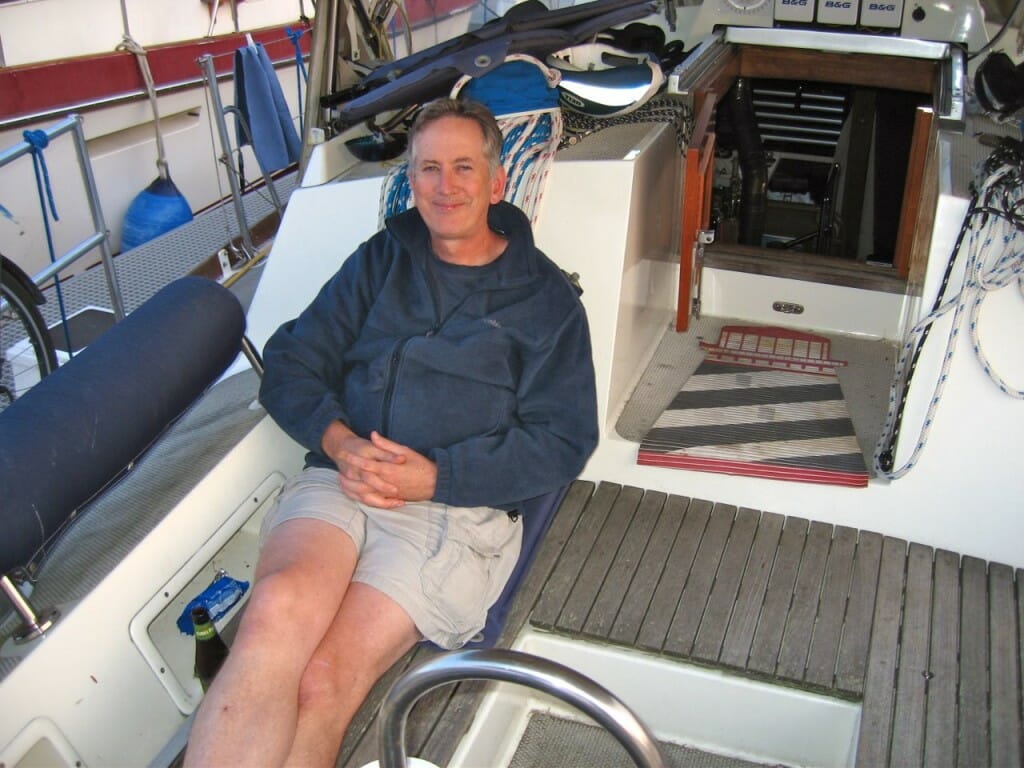
The Nomadic Research Labs Geek’s Vacation Program is back in full swing, bringing back excellent memories of the Olden Days in the BEHEMOTH and Microship labs. Brilliant techies would arrive from far-away places to dive into a project with me, contributing not only their own formidable expertise but giving mine a much-needed shot in the arm… whether through skill-building or just the motivation of working together. My old friend Tim Nolan designed the Microship 8-channel peak-power-tracking solar charge controller about a decade ago, and he just flew back to Wisconsin after 10 days here aboard Nomadness.

This time, we worked together on some of the ship power projects… notably installation of the forward photovoltaic array, along with extensive cruft removal and internal system upgrades. The beautiful stainless substrate for the solar panel was recently fabricated by Derek Peterson in Stanwood; Tim and I bonded six 30-watt modules onto this, bussed them into a series-parallel configuration, then wrestled it into place with some temporary wood fixtures at the interface between the panel and its support struts. In the photo, you can see notches on the sides to clear the backstays… and the extra metal border provides a little bit of mounting space for antennas and cockpit lighting.
The tan fabric under the boom is a sort of bimini that came with the boat; it zips to the trailing edge of the dodger and then ties somewhat clumsily to the arch. This will go away, with the new structure providing a starting point for a more robust cockpit enclosure… but it will do for the moment. The distant edge of the solar panel is supported by the radar arch, which also carries the cabling.

These photovoltaic modules were custom-made long ago by Solarex for the Microship project, and consist of a Tedlar-encapsulated sandwich with no metal backing… very fragile. The wires emerge from the back near the edge with little fillets of silicone; to clear these, we drilled 3/4″ holes with Cecil the milling machine (Cecil be ‘da Mill).
I agonized for quite a while over the proper adhesive for this project, having recently been driven a bit crazy by the problem of bonding neodymium magnets to aluminum brackets for the pilothouse curtains. Heat is the enemy, and even with preparatory solvents and surface-sanding I’ve had many of them fall apart from differing coefficients of thermal expansion (and lousy epoxy adhesion to the nickel plating). Solar panels get very hot, so I was concerned about the mess that could result from a poor choice of goo.

We decided to take a chance on high-temperature 3M VHB (Very High Bond) adhesive tape #4646, though the thickness of .025″ did introduce the risk of cracking the silicon wafers if we were overzealous during application. Time will tell if this was a good choice, but so far it has handled a few hot days without delaminating or doing anything else disturbing. I debated about leaving a little gaposis for outgassing, then imagined it being an ingress point for water that will freeze and decided against it… I might even double down on that conclusion with a surrounding fillet of sealant. (The tape pattern is a full perimeter along with a single strip down the center.)

Once the modules were bonded in place, it was time for the cabling… I slumped at the desk to rest my back while Tim took over with ratchet crimper and heat gun. We decided to wire them into a 24-volt series-parallel configuration (I would have liked a higher voltage to reduce I2R cabling loss as much as possible, but the total array size will be 14 modules once the second panel is mounted over the dinghy, and it doesn’t parse any other way). The bundle of red and gray wires will be spliced to a jacketed #10 cable, with another for the aft array of 8 modules; these terminate at an Outback MX60 solar charge controller, which maximizes the power point and pushes current into the batteries via a dedicated shunt (with an Ethernet connection to the other Outback power equipment to allow centralized monitoring and control).
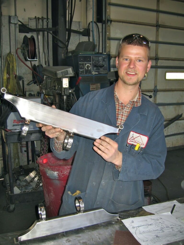
The final stage was installation… physically difficult, but simplified by Derek’s excellent design work, including the hinging fixture he is holding in the photo at left. I had previously done a test-fit of the frame once these were mounted to the top of the arch on either side of the radar, and that left one loosely defined TBDWL item (To Be Dealt With Later): the angled connection to a pair of support struts that terminate at split collars on the arch support legs (right).
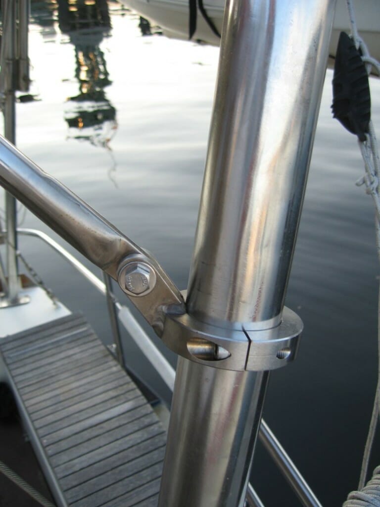
The top ends of the tubing struts contain three welded-in half-inch nuts; I chased these with a tap to work out the rather substantial thermal distortion, added stainless rod-ends, and then, with Tim holding everything level, pinned them to temporary chunks of wood that will be replaced by stainless now that we actually have something to measure. Nothing on a boat is ever parallel, square, or the same on both port and starboard sides… that’s part of their charm, I suppose, but it can turn fabrication projects into hair-pulling challenges.
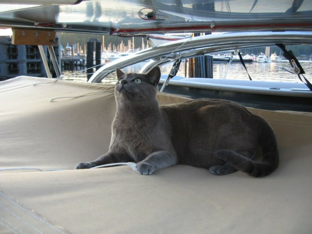
Most important: the new addition has received the Isabelle seal of approval. She now has a high soft shaded spot, complete with a bit of cordage to provide amusement! Here, she is checking the wire routing…
Other Power Upgrades
Tim’s geek vacation also yielded some other much-needed changes to the Nomadness power system. Looking at the relevant section of the To-Do List, we decided to focus on battery-management and shore-power issues.

Please don’t ever do this. These “terminals” were carrying 30 amps of shore power, mashed under screws on an old AC source-selector switch in an almost completely unserviceable location!
Much of this was in the category of cruft-elimination, and there are now three plastic grocery bags of extracted wire in the lab along with a few eBayables… including a triple battery isolator formerly used for the alternator, a smaller two-bank unit that once took care of a solar panel, and a galvanic isolator that was used to control stray-current corrosion. We also excised a scary old shore-power fire-starter selector switch with pitted contacts and redneck wiring. It’s really scary, sometimes, to go through this process and realize what I’ve been living with…
We didn’t change the business end of the engine-charging system (a vintage Lestek 130-amp alternator and a Balmar 4-stage regulator), but eliminated the downstream battery isolator that is basically three huge diodes with lots of cooling fins… allowing charge current to flow to multiple banks while preventing them from discharging to each other. But the cool kids these days are using a new device called an Automatic Charging Relay (ACR); I first heard of this when my marine electrician friend back in La Conner, Al Felker, suggested it while extracting an antique shore-power change-over relay that had been rendered obsolete by the Outback (and the inverter-charger before it… talk about relics!). These contraptions notice when charging is happening and connect battery banks together without diode losses… then keeps them that way until the state of charge drops far enough that isolation is needed to allow such niceties as later engine-starting.
While doing all this, we were hauling out old dead-end cables, discovering lots of naughty things like loads connected directly to the 690 amp-hour house bank (some without fuses, each a potential harness-melter or boat-destroyer). Every exorcised no-no added to the clarity and safety of the system, and the new drawing is much less confusing. This is all stuff I’ve wanted to do for ages, but I often need a rather strong nudge to start tearing apart things that work and are hard to reach. Huge thanks to Tim…

The final task of his time here was installation of the Charles ISO-G2 isolation transformer, which completely severs all direct connections between shore power/ground systems and those aboard the boat. This protects the hull from induced corrosion (which can be severe) and prevents delicate humans from providing a return path to shore through their bodies. All metal boats should do this as a matter of course, and I’ve been hauling this 60-pound monster around for a couple of years without actually hooking it up… largely because the AC side of my power system was such a mess. Now it is in place, and ground-isolation measurements are in the multiple-megohm range. In this photo, Tim is working on the jumper wires that parallel windings to configure the transformer for 120-volt operation (it also handles 240), with Isabelle doing quality-control checks on his crimping job. I bolted this down to the plywood substrate of the power bay, but the 60 Hz hum is quite noticeable; vibration-damping mounts are on order.
And then, a much-anticipated sailing day! We humans had a wonderful time tacking back and forth while exploring our new back yard in the San Juan Islands, but Izzy was not at all happy about it. She did manage to stoically ride it out until we docked… whereupon she bolted and tried to catch the ferry back to the mainland so she could hitchhike to the shelter and take another shot at finding a suitable human for the cat-support staff position. She got over the trauma, but clearly needs some more time on water… and she’s not the only one…

Curious about the effects on heating/cooling of the solar cells by mounting them on stainless. Do you anticipate any heat build up? Did you consider aluminum and or any sort of perforations in he base material? I do not know much about this, but would like to learn more.
Heating is a big issue, and indeed aluminum is a much more effective conductor… though structurally it would have to be thicker (or better supported) and would require anodizing. The surrounding structures are entirely stainless, so there is the substantial issue of galvanic corrosion. Of course, aluminum would be a lot more pleasant to work with…
Some commercial solar panels use stainless substrates, and at this thickness I’m not too worried about heat build-up (unlike the rather huge mistake we made in the Microship project, bonding modules onto a beautiful substrate that had a 1″ foam core sandwiched in okoume ply skins, an excellent insulator that raised the surface temperature substantially since the only cooling path was radiation out the top). But there are still two thermal concerns that bear watching: differences in coefficients of expansion relative to the silicon/Tedlar sandwich, and oil-canning of the entire sheet due to distortions introduced by welding to the tubular frame. At the moment, the bulge is positive, which is actually a huge feature… it won’t hold water and collect dirt. I have yet to find out what will happen when the boat is pounding, and any abrupt cycling in this mode will be hard enough on silicon and adhesives that I would consider it necessary to add support.
Perforations scare me a bit, given that we’re starting with this delicate custom module instead of a normal commercial marine panel that would certainly be my choice if I had deeper pockets. Even a galloping cat would create serious bending stresses at holes of any useful size, and there’s the small matter of the labor involved (I hate drilling stainless). An open fine-weave mesh would have been nice, but raises fabrication challenges.
This design is a compromise driven by having the Solarex Ultralite modules in stock… and I’m also taking advantage of the new stainless structures (this and the aft one yet to be installed) to provide mounting for antennas, lights, video, sensors, and so on. The aft one also includes a water-collection trough around the perimeter with two collection points.
But back to your question – yes, the cooler the photovoltaics, the higher the output. We must never put them in the sun! *grin*
Cheers,
Steve
Interesting data point, just now: IR temperature reading on top ranges from 120-139 deg F, and on the bottom 99-109. That may be partially due to the reflectivity of the stainless and the variable coupling internally (air and VHB tape), but it still seems like a large drop… full uniform bonding to aluminum would certainly be better for thermal performance.
I have my ascent solar panels in. they are about 1.5 mm thick. Now I’m trying to figure out what to do for bonding them to the dodger top. They are encapsulated in some sort of plastic and I have been unable to get any response from ascent solar. They do not answer the phone and they do not respond to messages. I bought the panels from a customer of theirs and they aren’t responding to the customer either. It looks like we will be doing some empirical tests. I bought 20 25Watt units and only have room to install about 14 of them so I can use one to experiment on. Because I bought 20 units I got them for 1 dollar a watt. 🙂
So my thoughts for adhesives is epoxy, 3m 4200 or 5200, TOP GUN® 400 Elastomeric Acrylic Urethane Sealant with Kevlar, maybe a silicone adhesive, thought about 3m tape but enough to do the job would be expensive.
I saw a sample of the top gun product and was really impressed with its adhesion and flexibility also it’s $3.50 a tube price. It flexes 800%.