
Antigravity, SSB, and Console Development
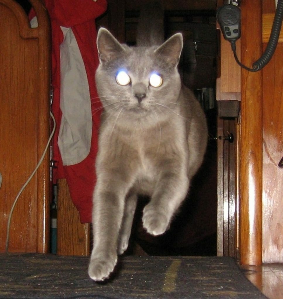
Time for an update! But first, a word from Isabelle, who has delicate sensibilities and prefers not to walk on the cabin sole when it needs to be vacuumed (although, like nature, she abhors a vacuum).
SSB Radio Installation
Now that we’ve dealt with feline matters, let’s talk tech. This first section is adapted from Issue #21 of the Nomadness Report.
Like so many projects that have been in the planning stages for a long time, my marine HF single-sideband radio gear has been sitting on the shelf for about 3 years. That translates into not having the latest version of the expensive PACTOR box, but otherwise the hardware is current: the Icom IC-M802 marine SSB rig and matching AT-140 antenna tuner are the same units I would choose if purchasing the rig today. In the developing comm console, this is joined by an Icom 706mkIIg for more flexible amateur radio use, Kenwood TD-D710A digital dual-bander, Wavenode for SWR/power monitoring, RIGblaster Advantage for digital modes, DSP speaker for noise reduction, and a few other things. But first, I needed to get the 802 cabled and online.

This is a perfect scale of project for a Geek’s Vacation (I welcome techie pals to participate in this project while spending a few days aboard Nomadness in a Pacific Northwest paradise), and I was delighted to host Daniel Collins a couple of weeks after Tim Nolan’s time here working with me on the power system. Daniel and I had struck up an enthusiastic correspondence last year… he was highly conversant with NMEA2000 networks and preparing his boat, Aletheia, for adventure. He got more than he bargained for… first a nasty storm in the Gulf of Mexico, then a dismasting and subsequent tow into Charleston after failure of a titanium tang. He’s now exploring retrofitting a junk rig on the Allied Princess, but is first taking a travel break… and I was happy to be part of that.
His visit was initially a dilemma; Daniel is such a clever chap that we had trouble deciding what project should occupy our week together! I had been assuming that it would involve the NMEA2000 network since he knows that stuff well and we’d already spent a fair bit of time on the phone chatting about design decisions… but the agility of youth trumped puzzles that could be addressed via email. I’ve been wanting to be back on the air with an HF radio for years, and installation on the boat would involve a fair bit of crawling into awkward spaces. Since he is also a radio geek, the choice was clear.
The radio consists of two pieces: a display unit that will be mounted in the comm console, and a “black box” that is the transceiver itself (as well as connection point for much of the cabling). With little fanfare, I bolted this to the bulkhead under the desk, where it can have more cooling airflow than it would have inside the enclosure.

This was not the physically awkward part, though. Daniel immediately jumped into that… installing the tuner on a bulkhead inside the hydraulics bay at the stern, then running GTO-15 feed line through a handy bit of gaposis into the lazarette, and thence to a clamping assembly at the bottom of the insulated backstay. The tuner matches this “random wire” to whatever frequency the radio is using, minimizing reflected power and keeping RF energy outside of the boat.
This is only half the antenna system, though. The tricky part is the ground, which is what this “pushes against.” Folks with fiberglass boats couple to seawater with methods ranging from bonding on-board metals or glassed-in copper screen to commercial products like sintered-stainless blocks or the popular KISS-SSB, but I have a steel hull that eliminates the need to do anything fancy… except for one little detail. Connecting the tuner to the hull would not only provide an excellent RF ground, but also create a DC ground loop that can drive galvanic corrosion. There needs to be a capacitor in there, transparent to the radio signal but opaque to direct current.

Lots of folks use disc capacitors, but they feel too fragile in this environment… so I talked to a few old-timers and went eBay shopping. This beautiful 1943 high-voltage mica capacitor from a Navy ship is just the ticket. Daniel did some metal prep to make a good connection and then bolted this to a hull rib… connecting it to the tuner via fat copper foil. This maximizes the ground current at these frequencies due to the skin effect, providing much greater conductivity than a piece of wire.
All this was done while wrapped awkwardly around a corner, and there was much grunting back there… but he emerged victorious. We spent a few hours stringing the two cables forward to the radio (tuner control and heavy coax), then turned our attention to power.
Radios like this need a solid battery connection, and should not be powered through a standard breaker panel. Here I was lucky… one of the many pieces of cruft slated to be removed from the boat is a LectraSan sewage-processing system, and it had a dedicated run of 4 AWG cable connected to a stand-alone 50-amp thermal circuit breaker. I re-routed it to the lab, and… the length was perfect.
Knowing that other radios would also need this beefy connection, I added a Blue Sea 6-circuit covered fuse block to the bulkhead in the “black box region.” (I was tempted to use a RIGrunner with its Anderson PowerPole connectors… but I have no desire to plug and unplug these rigs very often.)
With the Icom rig cabled to the fuse block, all that remained were the connections to its front panel, speaker, a ground, and a few more to bring the PACTOR modem into the picture. Fortunately, I had bought the whole package as a kit from Dockside Radio, including the modem, so it was all pretty much plug-and-play at this end. In fact, I turned away to feed Isabelle the hovercat, and by the time I looked back, Daniel had all the interconnects done and was ready for a smoke test.
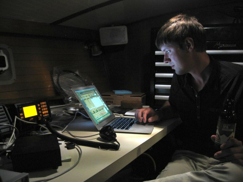
It worked! Since then, I’ve chatted with at least a dozen states as well as Japan and Brazil, and we set up a WINLINK email account, running under VirtualBox emulation on the MacBook Air (which is now on the air). In this photo, Daniel is looking at the Wavenode display that shows real-time power and SWR data:
Console Development
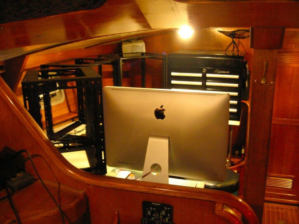
All the geekery that I’ve been planning and writing about for years is concentrated into a group of consoles distributed around the boat. These include ship operations and piloting (nav, engines, and power control); Internet and server tools (main computer, data collection, connectivity); and studio/communications/lab equipment (the rack spaces being mounted on the desk in the photo above). Here’s a page from a recent Nomadness Report that lists the console zones…

At the moment, I’m approaching all this on two simultaneous fronts. The original control panels in the pilothouse are being replaced by new surfaces milled from black .5″ King Starboard, and these hold most of the “normal boat stuff” like navigation instruments and circuit breakers. Down in the lab, however, the three equipment racks are getting black anodized aluminum panels packed with gizmology. By the time these are all done, it should all have a consistent overall feel… exactly what I’ve been fantasizing about since launching this project ages ago.
A huge part of the design process has been focused on usability… planning ahead for workflow, human comfort, logical clustering, and elimination of the need to run back and forth for related tasks. An example of the latter came with the boat: basic instruments and marine VHF were above the chart table across from the inside helm station, so it was impossible to steer, look forward, and talk on the radio (or select instrument modes) at the same time. Of course there are work-arounds, but the point is that attention ended up being split between control surfaces… even during routine tasks… a constant low-level annoyance.
In the pilothouse, the solution is obvious; just collect all boat-driving stuff in one place and make it purty. With the exception of a few things that I want to see from multiple places (like the stereo), the system pretty much designs itself around existing structures. So let’s instead talk about Geek Central:

This is my CAD system – Cardboard Aided Design. The three 12U rack units are in place (Middle Atlantic CFR 12-16, 21″ tall and 19″ wide), and temporary panels of Coroplast have been screwed in place. I spent many hours cutting up recycled file folders to make actual-size mockups of the electronic goodies, hanging them in place with tape, staring at it, playing “let’s pretend” with various scenarios, re-arranging, researching alternatives to some of the gizmology I don’t own yet, and otherwise refining it all into a system that should be pleasant to use. This informal use-case analysis with actual-size objects was hugely revealing, and it didn’t take long for it to start making more sense than it ever did in the form of planning documents. (I did this with the Winnebiko II and BEHEMOTH bicycles, even going on test rides with cardboard mockups taped in place… far more immersive than manipulating Mr. Template on a computer screen with 3D models.)
This is a solid starting point, and reflects all the known constraints, though I’ll probably bump into some mounting challenges as machining proceeds and make adjustments.
So what’s in this thing? Let’s take a quick walkthrough.
1. Audio
The left panel is mostly about audio (and a little bit of video). Keep in mind that there’s a 27″ iMac screen just to the left of this, though it has been shoved aside for the photo since I couldn’t get far away for a straight-on shot that showed all three panels. The largest control surface here, to use the buzzword of choice, is a 16-channel mixer… an Edirol M-16DX that has a remote physical box for most of the connectors. That makes it much more console-friendly, and joining it on the panel is a Tascam 8-channel Portastudio for recording. There’s also a small analog video screen with adjacent camera, a voice processor for podcasting, and a Crown rackmount Amp (XLS1000)… overkill but sweet. In the lower left, there’s a region for easy access to some connectors along with a few manual controls for audio-related hardware. A Fusion MS-IP700 marine stereo is located to the right in the central panel, and is the general utility amp.
I was originally hoping for a simple architecture here, like the Microship system. For that, back in the ’90s, we built an audio crossbar network with 32 inputs and 32 outputs, with 8 possible simultaneous connections all controlled by a node on the multidrop network of 68HC11 FORTH boards. Good times.
The problem is that I want true studio-grade mixing complete with insert effects, as well as the ability to smoothly manipulate a multichannel audio environment with front-panel controls. The crossbar concept could be extended to all this, but it would be a huge wheel-reinvention project… increasingly hard to justify when nice equipment is reasonably inexpensive off the shelf, compatible with all the related hardware including boom microphone, piano, and so on.
There is one bit of redundancy at the moment that is admittedly the result of GAS (Gear Acquisition Syndrome) more than actual need. The Fusion stereo is essential, with its iPod dock and N2K integration for multiple zones, and it’s a very capable Mode D amplifier with decent speakers available from the same manufacturer… so that’s central to the audio system design and will be on almost all the time. But at the moment, I also have that Crown amp, a much-loved product good for about 350 watts per channel. It will probably be the first thing to be reluctantly sold when I discover that there’s not enough room for all the front panel gadgetry due to packaging overhead or evolving needs.
So… why all this audio gear? In addition to normal entertainment audio, it will be my studio for podcasts and other audio production. All audio sources on the boat (including low-fi stuff from radios, speech synthesizers, computers, and such) can be routed either directly into the mixer or funneled to it via a switching network under control of one of the microcontrollers (node X). This will allow anything to be recorded, databased, transmitted, blared out the hailer horn, included in a production, converted to a stream, analyzed, or whatever. The region is also my piano studio, with a MIDI controller that pulls out from under the desk like a drawer, and the instrument voices (software or rack synth) should sound pretty spectacular in this small space. I am still trying to choose the speakers to mount with limited vertical clearance atop the wooden roof that will cover the three racks…
2. Communications
The central region will be the first one fabricated, and is largely devoted to radio gear. I rattled off a list of the ham stuff in the introduction to the SSB story above; all that fills a 6U rack in the bottom half. The upper half is more general: rack synthesizer, clock, the Fusion stereo mentioned a moment ago, Furuno NAVTEX receiver, and a docking spot for an iPad Mini that presents a browser for interfacing with the control system along with Facetime and other apps.
The “use case” for the radio gear is conventional… hours of sitting and peering at displays while twiddling knobs. I’ve been a ham for most of my life, so this is an important part of the ship system. Hope to catch you on the air!
3. Lab Equipment
Finally, this environment wouldn’t be called a lab without a proper suite of test equipment. I’m still fine-tuning the wish list with very tight panel real-estate constraints, but there will be a digital oscilloscope, multimeter, function generator, bench power supply, hot-air rework/soldering station, utility connectors for development-related stuff, and local power distribution.
There is a trade-off here, as some tools are better kept free-floating for use wherever needed. The console won’t replace a handheld Fluke DMM or the butane soldering and hot-air tools, but in general I want to eliminate the clutter of things that have to be hauled out and put away with each use. Space aboard is very tight, and one of the primary goals of this whole console project is to bring everything under one roof where it will look and feel like a single system.
I have not yet settled on the specific instruments for this region, though some favorites are emerging from hours of immersion in the excellent EEVblog and its forums. I’m lusting after an all-Rigol suite, but that’s pricey… not nearly as much as Agilent or Tek, but still a binary order of magnitude above the cheapies. We’ll see.
In Other News…
I’m yet far from having the new shop space in Friday Harbor running smoothly, and there is still a mountain of tonnage that was offloaded during the move (and I still need to fetch the Microship from my old place on Camano Island). It is shaping up to be a great workspace, though, and the plan is to bring the mobile-lab trailer inside to provide a shirtsleeve office environment during the winter and reduce heating requirements to the actual shop area (not the huge high-ceilinged open space).
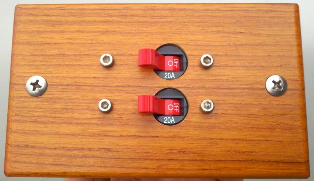
The boat’s power system has made significant headway since my August post about forward solar array fabrication. I milled a little teak panel for the array breakers, cabled them to the Outback FLEXmax 60 controller, and tied that into the battery bus via shunt… it works beautifully. The system now has the company’s new MATE3 display, which is spectacular! Not only does it have a network interface for data collection and local storage on an SD card, but the unit itself provides graphic history displays that make it a lot easier to observe what’s going on in the power domain.
This is shaping up to be subject of the first in my series of Boat Hacking Design Packages… eBooks that fully document various parts of this ship. These complement the Nomadness Report series, which can be thought of as a detailed magazine-style narrative of the project. I’ve published 191 pages since I started this last April… but what if someone wants a focused picture of one subsystem without having to wade through a hundred other topics?
The Design Packages address this, including schematics, mechanical drawings, component sources, and so on. I’ll resist the temptation to try to turn them into definitive works about each topic (impossibly ambitious anyway), limiting their scope to actual working systems on this boat. This puts them in the same category as appnotes, white papers, and old trade-journal regulars like “Ideas for Design” and “Designer’s Casebook.” These were always the first places I would turn when approaching a project: starting points that are known to work, helping avoid wheel reinvention. My hope for this series is that it will serve this purpose for fellow boat geeks (though sidebars sprinkled throughout will mention alternative methods or competing products).
Enough work has gone into the power systems to make it a good choice for the first of these eBooks, and I’ve started converting a clipboard of sketches into proper 11×17 drawings. Should be a fun one, following electrons all the way from shore/solar/generator sources, through the battery management system, and out to distribution… complete with monitoring tools.
View from the Top
I’m closing this post with an amazing photo taken by my friend Voytec Wacowski who visited last month. One of the items that has been on my to-do list for ages was to clamber to the top of the mast, feed a line through a sheave for a little utility platform project, and examine the bird-shattered remnants of my masthead light so I know how to prep the LED replacement. He fearlessly ascended and took some photos, then returned to deck level and said through a grin and thick Polish accent: “this is instance of your Tom Sawyer fence-painting principle.”
Of the 50 or so photos he snapped aloft, this was the gem. Nomadness looks like she’s docked to the Space Station…
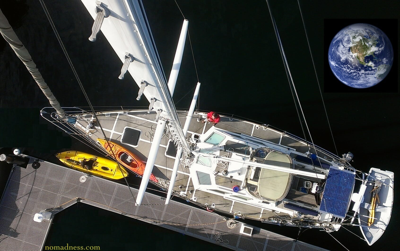
Photo from masthead by Wojciech Wacowski, with a little help from NASA and my editing tools.
Cheers!
Steve
Please add me to the announcement list for your “Design Packages.”
Noted!
It is enormously cool that you used a component built in 1945 as part of your radio setup.