
New Microship Status list
This was the beginning of a series of posts to a mailing list of folks interested in participating in the Microship project, which was just in the process of landing at UCSD in anticipation of providing context for student projects in the 93-94 school year. I was still scrambling to find space on campus, and was rapidly refining the design, chasing sponsorships, and getting to know students. This list grew into what later became the Microship Status Reports, but at this stage it was just a series of email updates with the “subscribers” pasted into the BCC: field.
Steven K. Roberts
UCSD Microship Lab
August 4, 1993
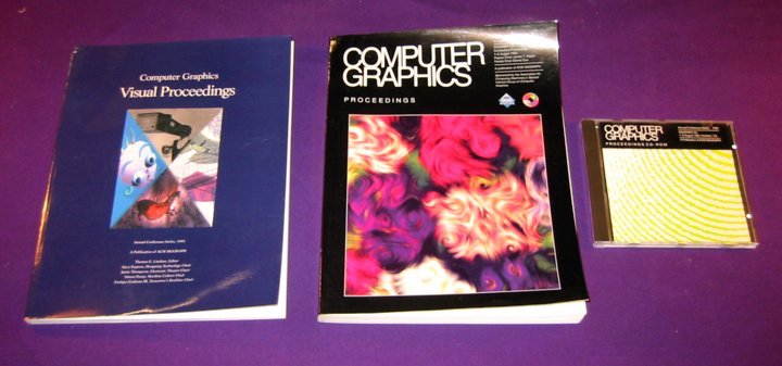
Just back from SIGGRAPH, a thoroughly entertaining show (my first time — been trying to make it to one of these for years). While it’s generally rather remote from the kinds of things that concern us here, it did provide some useful insights into video editing, video conferencing, CAD, and presentation packages.
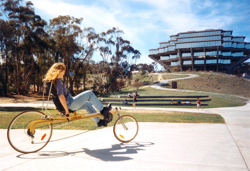
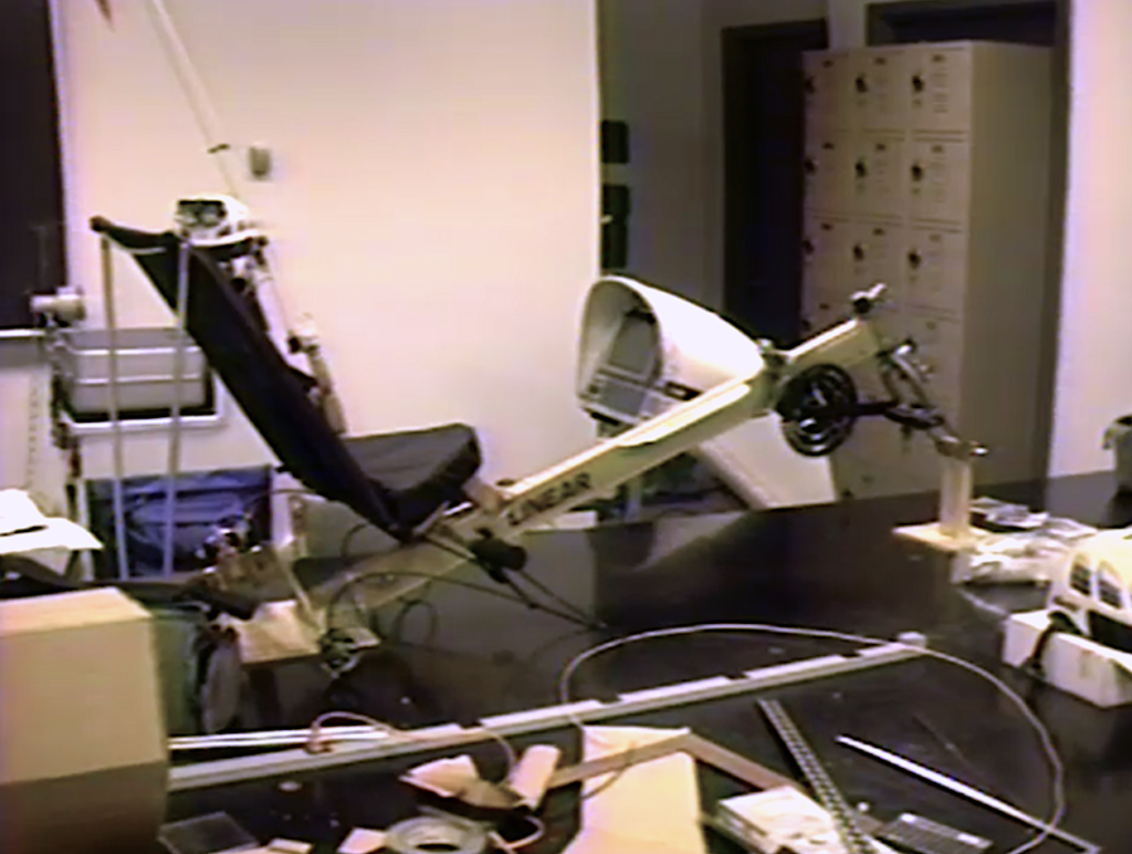
I returned today to find a large box in my office — the Linear Recumbent donated by the manufacturer! It’s gold anodized, and looks great (photo above is a friend riding it on the UCSD campus). Two immediate plans: try it with 16/20″ wheels instead of the standard 20/27″ pair, since the large wheel will be very difficult to stow on board the Microship. Second, I want to build a simple base of 2×4 lumber to support the bike (without wheels), then construct a hull segment and console assembly mockup out of cardboard and hot glue.
This will help a LOT in visualizing what has to happen in this critical area of the boat, since human interface via CAD is way too abstract to be satisfying. It may even be possible to link the recumbent handlebars to the rudder, perhaps with a lever to lock the helm in any position and a method of coupling it to an autopilot. But first, we need a reality check: will it fit, and is the seating/pedaling position comfortable?
Motorola’s new Traxar + arrived — a replacement for the one they gave me when I visited in Chicago early this year. It is differential-ready, and has vastly improved algorithms for fast acquisition and tracking. The other one goes back as soon as I can find someone to sit down for an hour and transfer the waypoints I’ve stored to a file. Shipping soon – their CORE unit to be built in.
Info arrived today about reefing/furling rigs, the Power Survivor desalinators, and a line of nautical computing products handled by DF Crane here in San Diego.
Some boat design thoughts
I’m considering looking at other options for the center hull (“vaka,” in South Pacific parlance), including an ama (outrigger) from a commercial trimaran or custom <shudder> fabrication. There are just too many issues that don’t mesh well with kayak design, and the deck is now completely custom. Besides, a bit of vee in the hull might eliminate the need for a clunky leeboard. The outer hulls, however, will definitely remain as single sea kayaks — a major design goal is to have agile and seaworthy boats for escape or play.
But the main hull is the hard part. I’ve made a preliminary sketch of the bulkheaded bays, which break down as shown below. Bays from now on are numbered by a prefix letter (V for vaka or center, since V even LOOKS like the main hull in cross section; P for Port kayak; S for Starboard kayak) and a number counting from the bow. This nomenclature will appear in cable drawings and mechanical artwork. Here are the eight bays of the Microship’s center hull, at least in this preliminary design stage:
- V1: Flotation and light storage. Deck fixtures include Qualcomm antenna, forestay, bow light, tow fixture, locking cleat.
- V2: Electronics enclosure, pressurized, removable from bay for service. Bay itself contains compressor, tank, sealed battery box. On deck: whip antennas, air intake, GPS antenna, and probably a lot more to be defined as this goes on.
- V3: Head, holding tank, medical kit (this is the beginning of the tented zone in water-bivouac mode and is immediately aft of the mast step and forward beam assembly). On deck: bimini for head privacy, folding cover.
- V4: Console, on top of cockpit area. This will be pressurized directly, and contains all LCDs, related computers, and controls. On deck: compass, RF LAN antenna.
- V5: Cockpit, bike, emergency gear, water server, head-cooler fixture, all ready-access gear. On deck: sail controls, manual bilge pump handle, grab lines, bimini for sun protection or foul weather.
- V6: Ready storage hatch for food and gear. On deck: PFD lashings, grab lines, waterproof speakers. (end of tented zone).
- V7: Water processing (desalinator, filter, tank), environmental data collection, Peltier cooler. On deck: probes, fridge airflow, whip antennas, mainsheet block.
- V8: Flotation and rudder mechanicals. On deck: thruster assembly (flips down), radar antenna tower with steering vane and insulated backstay fixtures.
Other random recent design notes
The Microship Control System (MCS) screen should be small and passive (not VGA), and the associated system ROM-based and solid. I was creeping toward a 486 or something to take advantage of available software, but this how the BEHEMOTH Effect starts. The control system has to be extremely reliable, not a place to run random apps and fiddle around with hard disk management.
We need to see if the Furuno radar image can be exported to the video system (some radars allow this). I’m trying to minimize console real-estate demands by integrating displays, though for maximum reliability we should leave this intact and use it as a nav sensor display as well (in case MCS crashes) since it accepts NMEA 0183 data from GPS et al.
The trailering issue is critical and has to be addressed from the start: let’s see if we can use the beam assemblies in a second mode that helps support the whole system for road mode (behind a motorized tow vehicle, though maybe the bike for short distances on level ground). Without this, the security problems when in port will be much greater.
Audio/video system: there should be four cameras on board — the 360 degree turret on the bow (azimuth only), an over-the-shoulder shot from the radar tower, a tight head shot from the console, and handheld. A video switcher must route these, as well as possible screen captures and VCR signals, to the video deck, video conferencing system, and frame-grabber. Looking for light, low-power cameras that lend themselves to sealed packaging and remote control.
Enough for now. Good to be making some progress!
Steve
You must be logged in to post a comment.