
Increasing Solenoid Speed – Machine Design
Back in the late 1970s, I was blending my consulting business with a budding career as a freelance writer. One of my rules for myself was that every project had to yield at least one published article, and this one fell out of a machine that I built for Robinson-Nugent, a manufacturer of IC sockets and other connectors. The system had to detect insertion and withdrawal forces on the fly using a pin attached to a load cell, then reject an out-of-spec socket by kicking it off the fast-moving carrier with a solenoid-actuated mechanism.
The solenoid had to move so quickly that I needed to hit it with high current, but it was also possible that a bad run of parts could keep it energized for a long time… long enough to burn it up if the current were not dropped back to a holding level. This called for a two-step driver circuit, which was of enough general interest to make it into the pages of the “Tech Briefs” section of Machine Design.
A footnote to this story is that I had an oversight in the schematic, which an engineer in Ohio spotted and brought to my attention. A diode should be added in the collector circuit of the bottom 2N3055: cathode to the collector and anode to the junction of the solenoid and the other driver transistor. (Thanks to the keen eye of R. E. Smith of NCR, I dashed over to Robinson-Nugent and soldered a diode in place… probably preventing a later service call and much head-scratching!)

by Steven K. Roberts
Cybertronics, Inc.
Machine Design
January 26, 1978

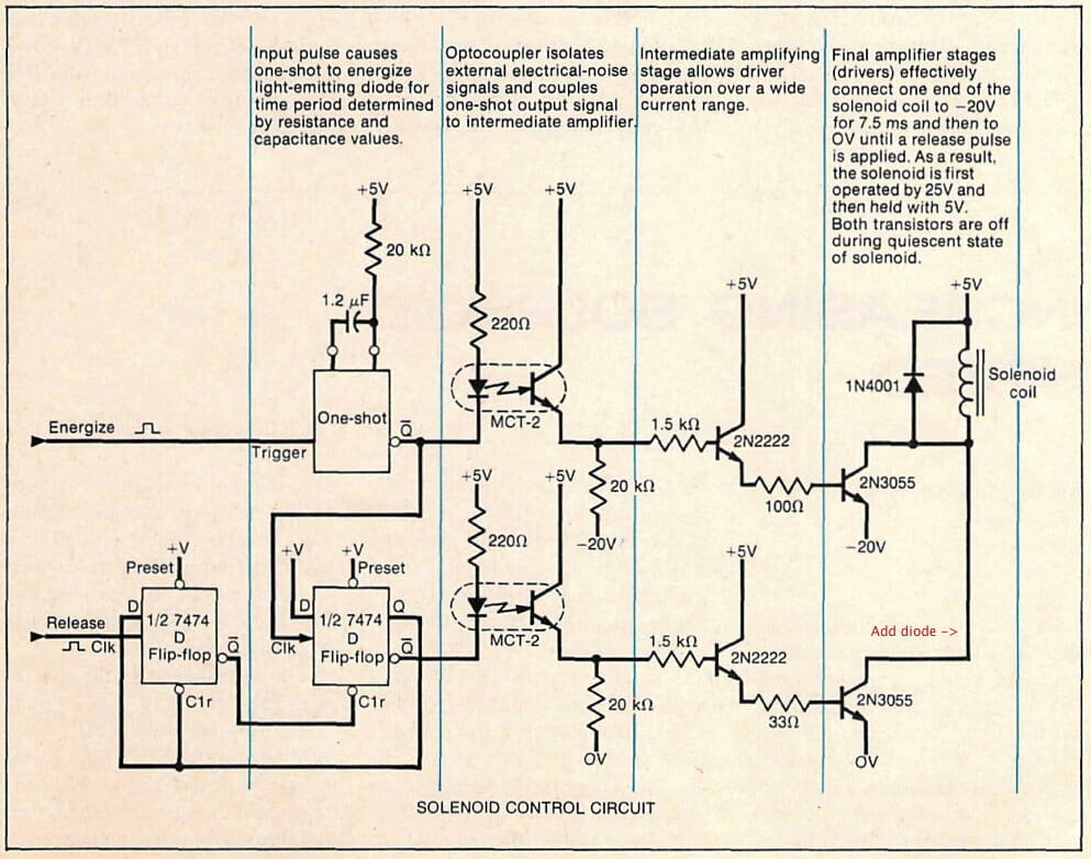
COMPLETING a mechanical action in a very short time often requires pushing an actuator beyond its normal speed capability. If the actuator is a solenoid, its thermal limitations may be an obstacle to faster operation. For example, increasing the applied voltage increases force and actuating speed, but the duty cycle must be decreased to prevent the solenoid from overheating. This limitation can be overcome by using the circuit shown here.
Upon application of an external pulse signal, the circuit applies a high energizing voltage to the solenoid for a brief time period—in this case, 7.5 ms. Then the circuit reduces the voltage to a level (typically 20% of the original value) that keeps the solenoid actuated indefinitely without excessive heating. This approach not only accelerates solenoid action safely but also allows a single solenoid size to be used in a wider range of applications.

The curves show the operating characteristic of a typical solenoid controlled in this manner. Referring to the circuit diagram, the 20-kΩ resistor in the one-shot circuit may be varied manually or with a selection circuit for full control of the high-voltage time interval. A pulse applied to the second input of the circuit de-energizes the solenoid.
Other modifications to the design may be used to effect any degree of control over the applied current, such as adding other stages to switch intermediate voltage values. In all cases, specific design parameters should be determined from the solenoid manufacturer’s literature.

You must be logged in to post a comment.