
Sailboat Power Console Fabrication
Steven K. Roberts
Nomadic Research Labs
One of my frustrations with this boat has been difficult serviceability in a very critical place: power-distribution. This a region that needs to have easy access, excellent lighting, clear labeling, and a lack of clutter… not only is it otherwise maddening to make changes, but it can be a serious safety issue. (Thrice over the years I have found burned wires and had a hard time squirming in there to fix them; many boats have been lost to this sort of thing, and it should never be difficult to access a nexus of power cabling!)
A few months ago, I wrote about the first phase in the fabrication of the new Nomadness pilothouse console (upper helm panel). I used black half-inch King Starboard as a substrate, machined holes for the instruments, and added a hinge structure with simple latching system to keep it in place. I did that one first because it was relatively easy… sort of a practice piece for this new one.
The original panel hinged up, suited more to a willowy contortionist than a big galumphing guy with back problems; the new one hinges to the right, and thus had to be shorter to clear the structures overhead. That offered a perfect opportunity to add that little louvered vent, which allows fan-driven airflow through that equipment bay when the Outback inverter-charger is maxed out, recharging low batteries.
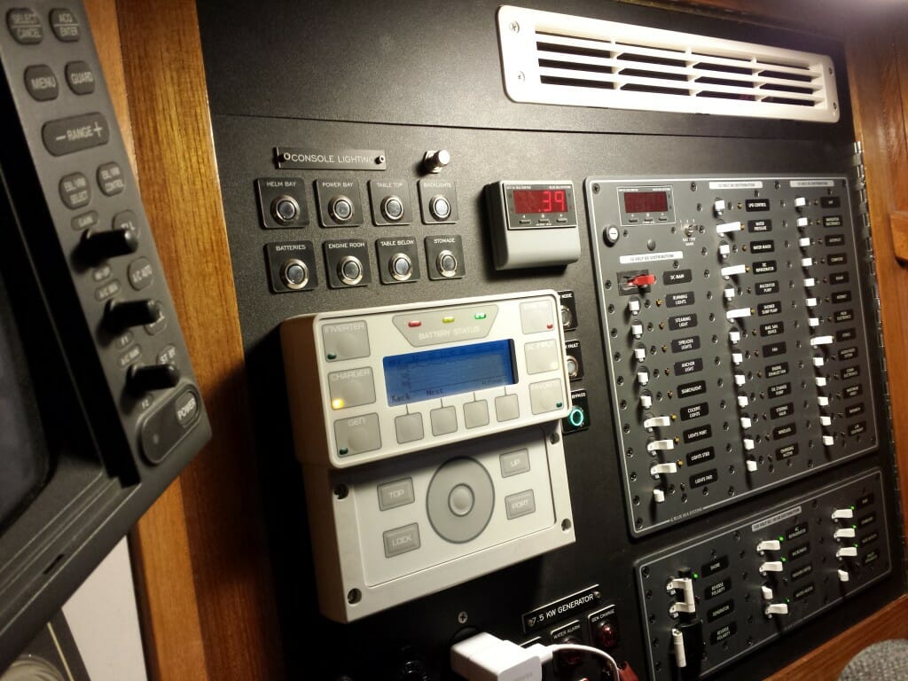
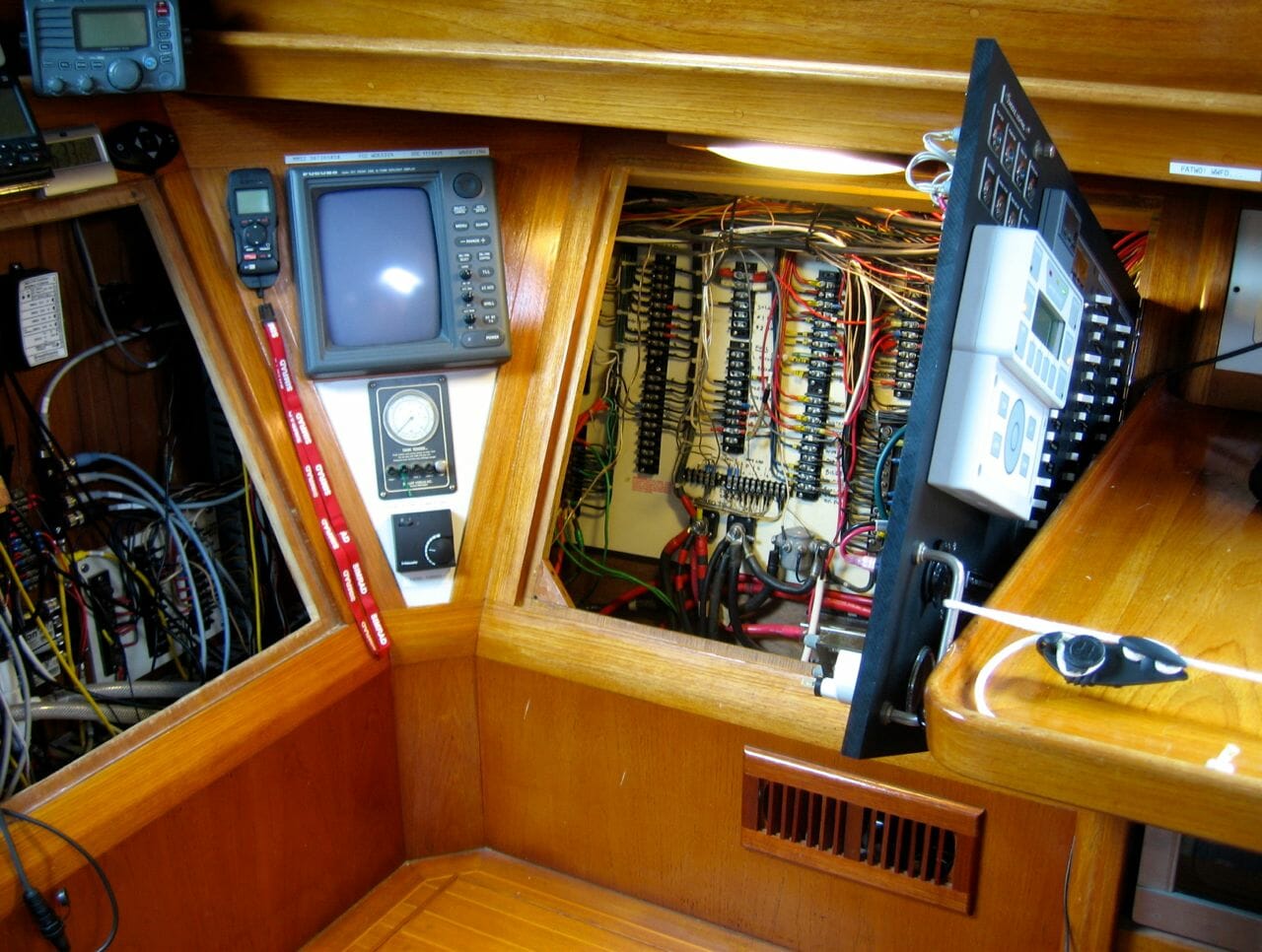
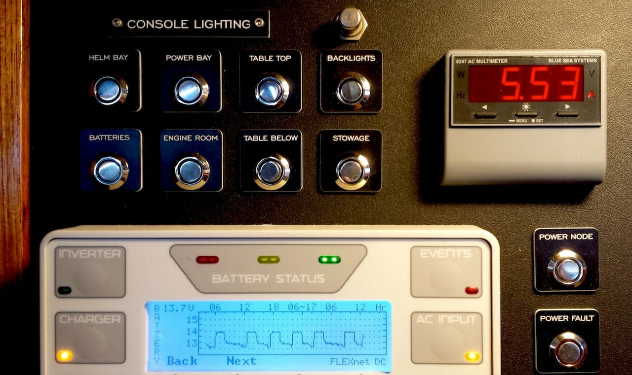
Difficult access into the old power console translated into my not dealing with things, so the boat’s power system has been rather opaque since I’ve owned it (not helped by ancient out-of-synch documentation and cruft left over from long-removed hardware). Now that I’m taking a top-down approach, nothing is connected unless it is actually relevant… and there is a satisfying mountain of old wire in the lab. The effort has already been worthwhile, for it is now a pleasure to work on the power panel:
We’ll get into how that works in a moment, but first let’s look at the overall design and fabrication process.

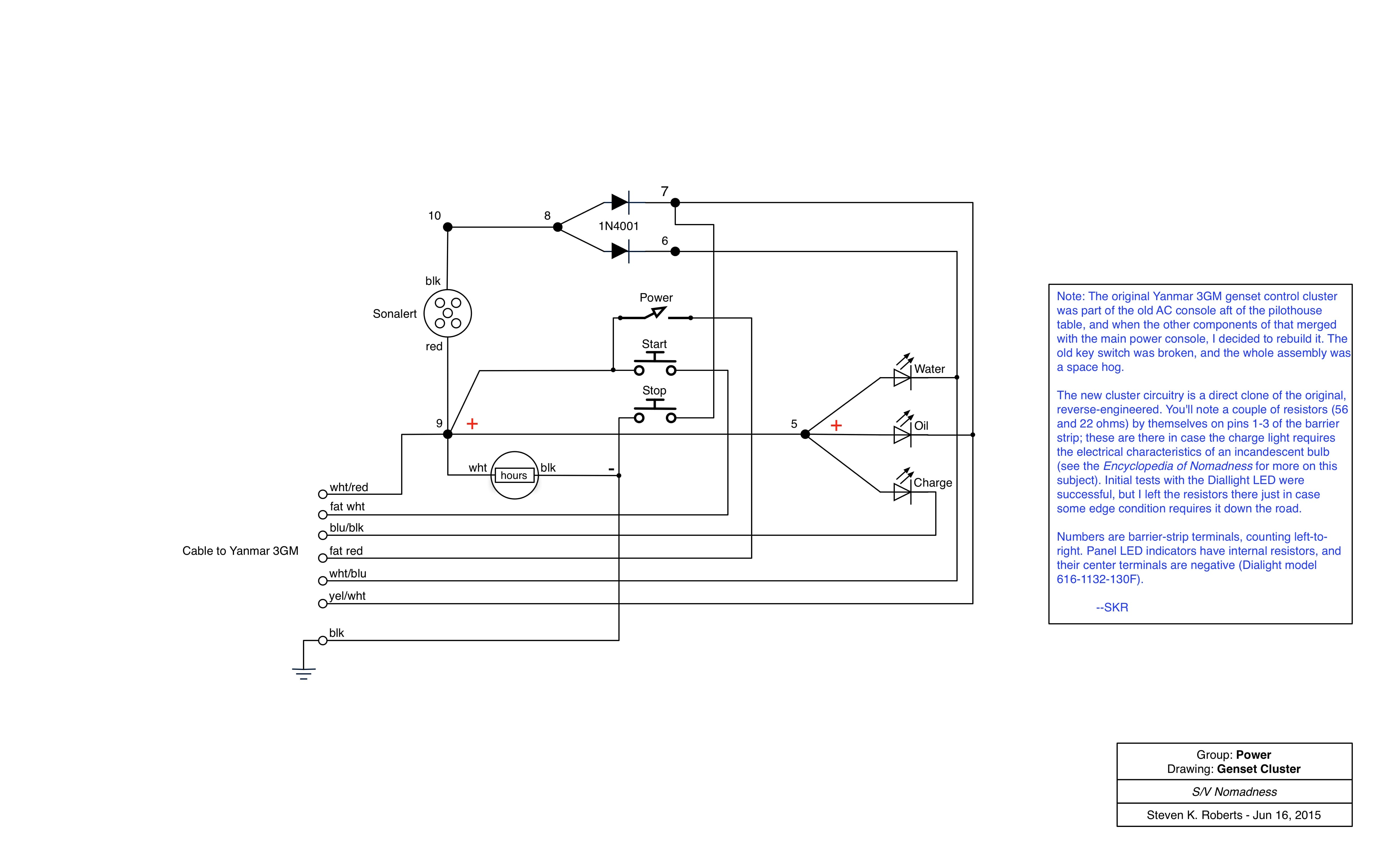
In this photo of the boat just before I acquired it, you can see the original pilothouse. That area off to the left (over the chart table) is becoming the network console, with the data collection stuff all just under the tabletop; the control panels around that chair are being completely re-done. It’s not visible in this picture, but the most awkward area was off to the right and just out of frame… another panel that was even harder to use than the main one, carrying AC breakers, a cluster for the Yanmar generator, and controls for a long-gone watermaker. For years, I’ve been eying that region with thoughts of converting it to galley-related stowage, so I decided to blend all AC and DC controls into the new integrated console. While this does raises a few safety issues, it’s nothing that can’t be overcome.
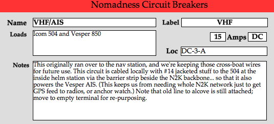
Since this change involved new breaker panels, I spent quite a bit of time fine-tuning the list of circuits and trying to think far enough ahead to accommodate future additions. I threw together a database (FileMaker) that gave me a place to keep notes, locations, and related data for the 80 or so circuit-protection devices on the boat (including random fuses). A typical record is shown here, though I found that it was most useful showing groups as a sorted table.
Since this was to become the central cluster for all power-related controls and displays on the boat, fabrication was slowed by over-thinking… a maddening process, but one that eventually pays off. Here’s what ended up being mounted:
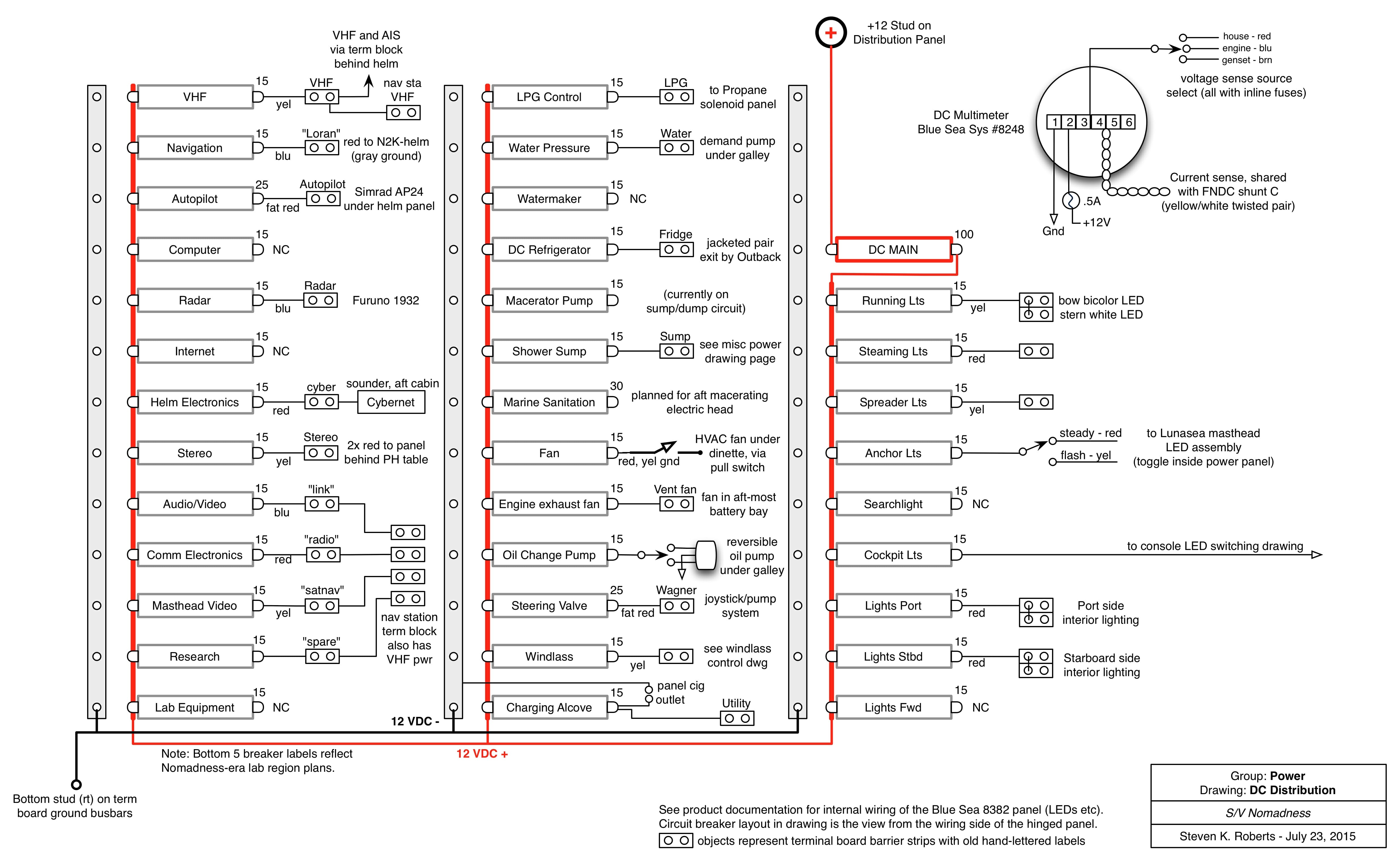
- DC breaker panel (Blue Sea 8382) with DMM, 100A main, and 35 positions
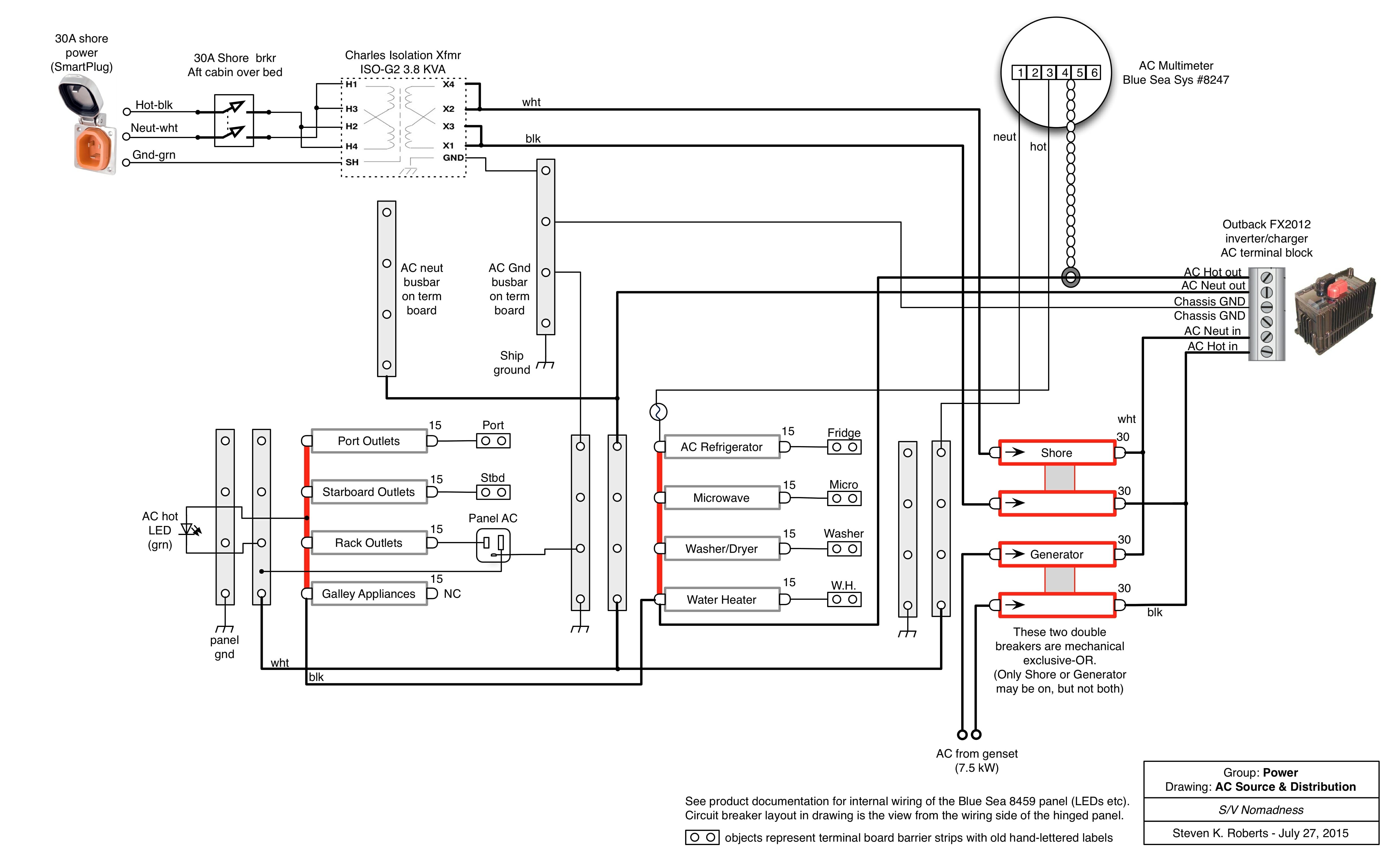
- AC breaker panel (Blue Sea 8459) with source-select 30A breakers and 8 loads
- AC digital multimeter (Blue Sea 8247)
- MATE3 control/display unit for Outback power system (2KW inverter-charger and solar charge controller)
- Yanmar 3GM generator control panel (homebrew)… on-off, start, stop, alarm LEDs (with audio behind panel), and run-time meter
- Green status LED for Blue Sea ACR and override button to disconnect
- Two ring LED/pushbuttons for Power Node status and fault alarm
- 12-volt DC utility outlet on the Charging Alcove circuit
- 115-volt AC utility outlet on the Rack Outlets circuit
- Grab handle that lashes to desk edge to provide support when open, with nearby hole for thumbscrew to lock closed
- Eight latching buttons with blue ring LEDs and legend plates for local lighting… pilothouse table, power console interior, helm console interior, pantry interior, under-table, battery bay, engine compartment, and control surface floods.
Panel dimensions (27.5″ X 19″) were defined by existing framing, so I started with a piece of half-inch Starboard cut to size with clearance for a stainless piano hinge, then amused myself for days by nudging objects around on the surface while imagining use cases, interactions, cabling, aesthetics, safety, lighting, upgrades, room for stuff on the back, and a rational layout that will have to make sense to somebody after I’m long gone. A few things were obvious, like putting breaker panels close to the hinge to prevent other devices from being obscured by bundles of heavy wire; others were more in the domain of intuition. To aid in visualization, I used a low-tech modeling system that involved blue tape, cardboard, legend plates, and the objects themselves… continuing this process iteratively as machining progressed, until it was done (the curse of perfectionism).
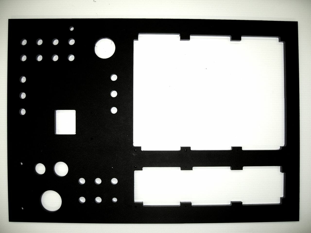
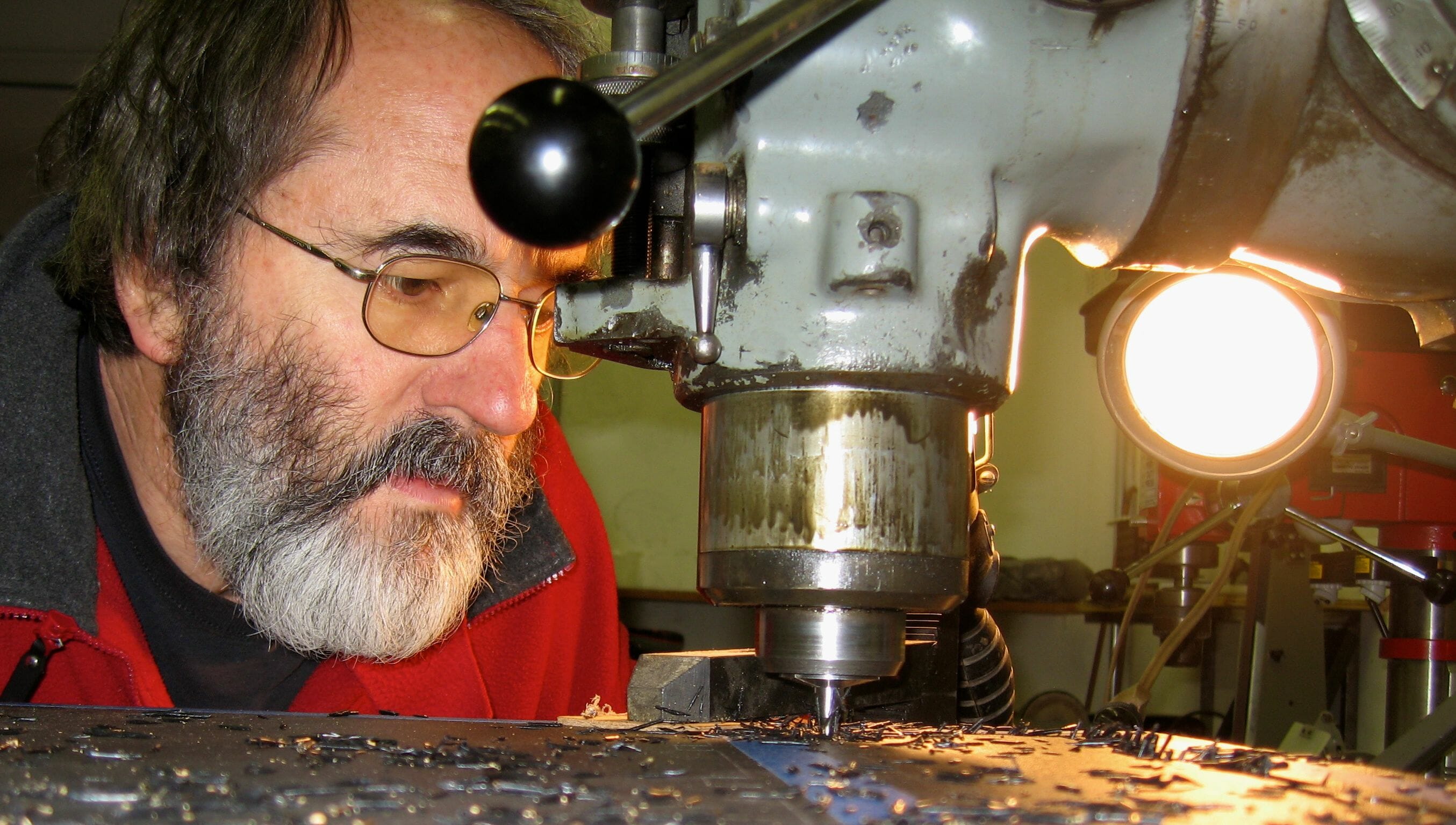
Eventually, with the help of my trusty Bridgeport, I had a chunk of high-density polyethylene with holes for everything. In the photo, you can see the detailing that was necessary for the Blue Sea breaker panels… the “bolt circle” for mounting is inside the outer envelope of hardware, which makes for a compact installation but complicates the hole cutouts (their newer 360 Panel family is much easier in this regard, though I personally prefer the look of the traditional series). The photo also shows a large round hole at the top for the AC digital multimeter, positioned to line up with the DC one built into the breaker panel, as well as a square hole for the two Ethernet cables that go to the Outback MATE3 controller.

Of course, no task is ever as simple as we expect it to be, so some of those holes required spot-facing to accommodate components that don’t play nicely with a half-inch substrate (in the photo above… toggle switches, Dialight LED indicators, the grab handle, and an old AC outlet all required additional attention).
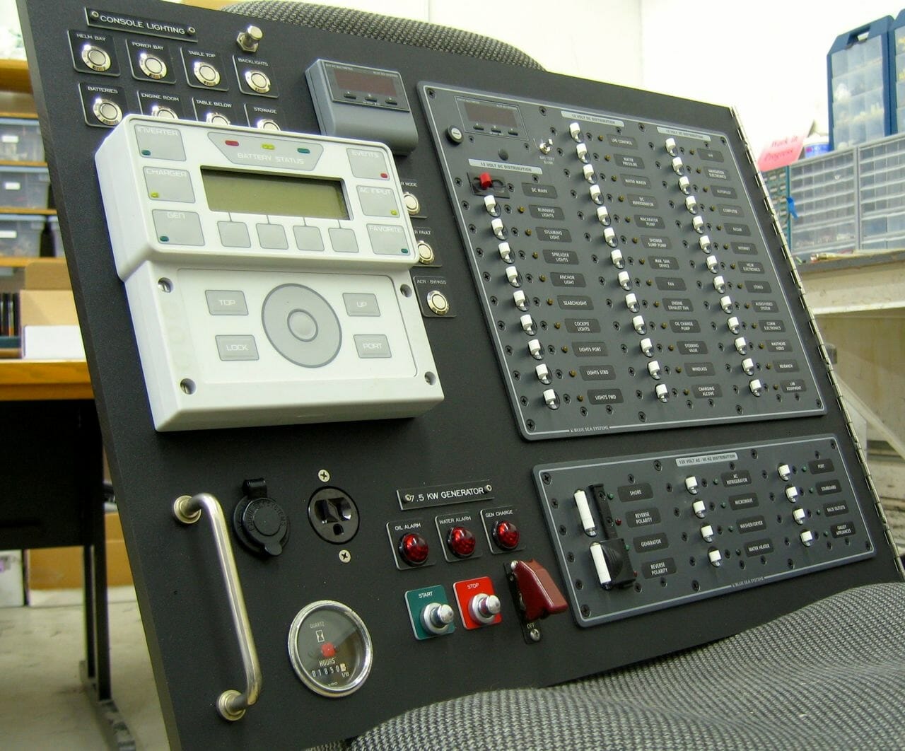
At last it was time for the fun stuff! I pre-assembled the panel in the lab, using laser-etched legend plates to label the buttons and indicators (those folks did a beautiful and quick job, not expensive at all, a perfect match to the 16mm holes required for the buttons I bought from Adafruit… like these blue momentary ones… though I have noted that blue LEDs get very warm and the green ones not at all). The cluster of controls at the lower left replaces the old Yanmar generator panel, and the adjacent grab handle was positioned relative to other hardware so that would be the only thing impacting the edge of the nearby tabletop when the panel is opened for service. Given the physical difficulty of doing the actual hinge mounting, I was putting a lot of faith in templates and measurements at this point, but I was on a roll…

It made sense to do some of the fiddly wiring in the lab while I had more room to work, so after playing with backlights and breaker blinkies for a while (who can resist?) I installed a barrier strip for the eight pilothouse LED circuits and wired all the latching buttons. While it might seem redundant to have lights that light up to indicate that lights are on (!), half of the latter are in enclosed spaces and easy to forget… so this provides at-a-glance status along with a big button to let me quickly go dark without losing the setup configuration or taking down other loads on the same circuit. This is a lot of work and expense, but I have come to realize that one of the biggest problems with serviceability aboard is simply not being able to see what I’m doing… adding decent lighting has already improved the galley immeasurably. I want it everywhere.
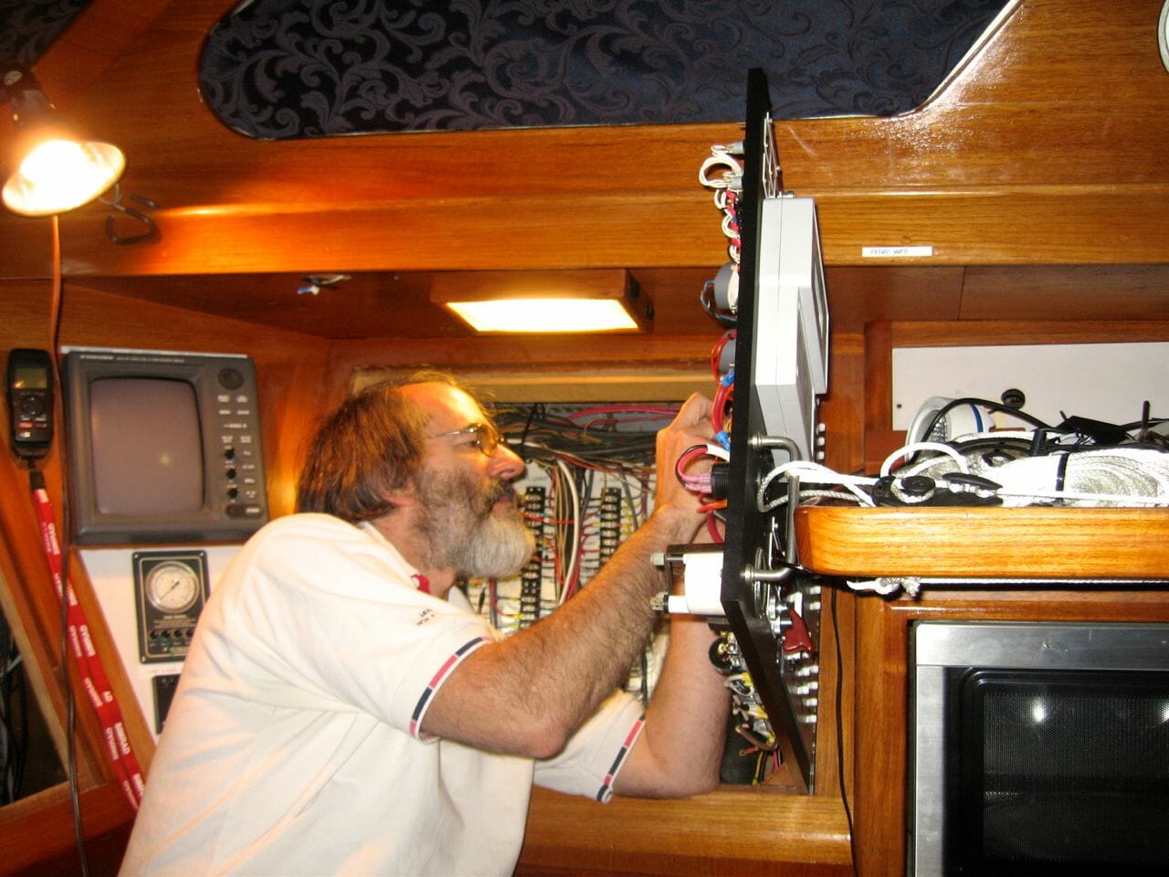
With this and some other pre-wiring done, it was time to haul the thing aboard, disconnect and extract the old panel, mount the new hinge while hoping for a successful fit, then hook up at least the bare-essential circuits for lighting/water/refrigeration. Before long I had a thicket of wires dangling inside the power bay, labeled with blue tape, then wrestled the new panel into place… propping it up with a stack of books while installing the piano hinge screws. There was a huge sigh of relief when it closed smoothly and snuggled into the frame.
One of the things in the TBDWL category (To Be Dealt With Later) had been how, precisely, I was going to hold the panel open in a working position. I had carefully arranged components so the handle would be the only point of contact with the table edge, but my to-do list vaguely referenced some kind of “latching system” that I was having trouble visualizing. As it turned out, the problem was trivial to solve with a scrap of stretchy 3/16″ nylon braid, a carabiner, and a Mini RopeTie. It takes but a few seconds to clip on to the handle, toss a loop around the table, and conjure an instant trucker’s hitch to keep the panel solidly in place while I work inside the console. (Later note: after this failed a few times, I got rid of it and fitted a simple latch hook under the table that engages the grab handle… much more elegant.)
From here, it was mostly a matter of wiring, with even more cruft finding its way to the scrap pile. Once the DC essentials were online, I did the same for AC… vastly simplifying the system in the process. In the old configuration, raw AC appeared on the terminal board behind this region, then was hauled via fat welding cable across the table to the breaker panel with all the switched circuits returning to labeled barrier strips. This was a lot of wire-tonnage, confusing and hard to modify… so it is now local and simple. Here’s a look at the back of the new AC panel:
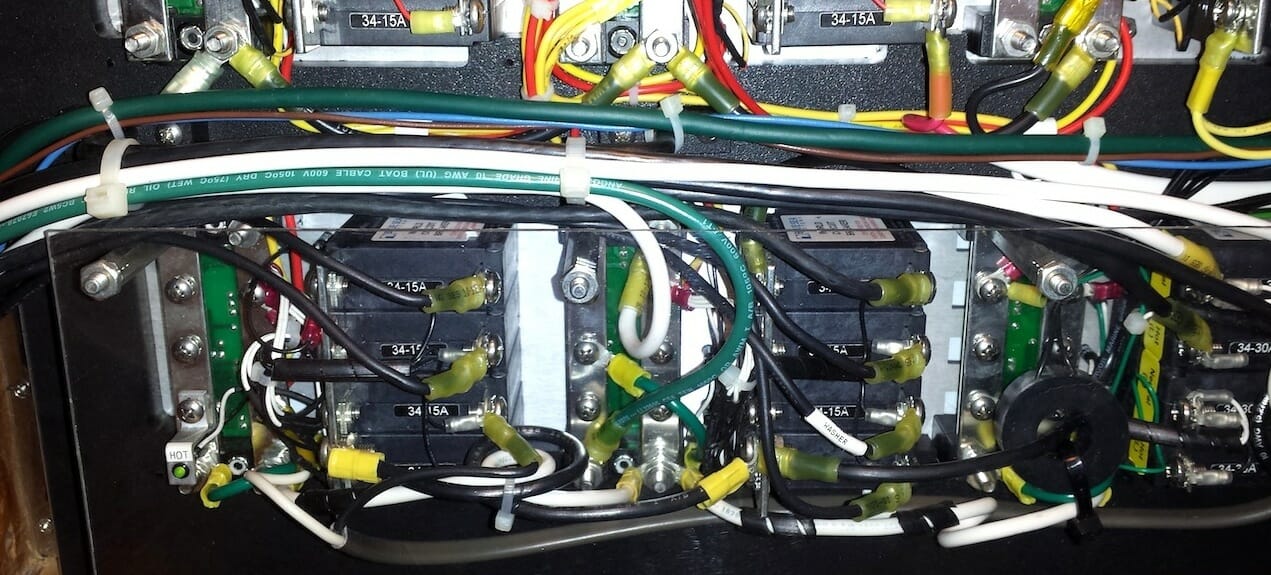
In the photo above, you can see the black current transformer that is used to determine the AC load for the front-panel multimeter. The bundle of wire going off to the left (where it turns down to exit in parallel with the hinges to minimize cyclic flexion) splits immediately into two distinct groups… eight switched load circuits to a labeled barrier strip, and all the heavy stuff related to the shore/generator input side that includes an isolation transformer and the AC section of the inverter/charger. Meanwhile, all DC cabling heads up in the opposite direction, so one can tell at a glance which bundle of cable contains lethal voltages.
Still, I was concerned about the exposed back of the AC breaker panel itself, so I added tall stand-offs to extend three of the studs supporting the ground buses, then used those to support a clear polycarbonate safety shield. This keeps stray fingers and tools from accidentally contacting high voltage when the panel is open. Just to be sure, I mounted an LED on a little bracket labeled HOT… indicating that things are alive in there. Also, while it is not very visible in the photo, the wire bundle is zip-tied to a black aluminum handle mounted to the panel (with another one at the top for DC). These keep loading stresses from tugging on crimp terminals and breaker screws.
Already I have noticed a huge difference in my interaction with the ship’s power system. The status of circuits is obvious at a glance, all switching is in the same region, and the “situation awareness” added by the Blue Sea multimeters and Outback display keep me constantly aware of what’s going on. I notice the Automatic Charging Relay, water-heater cycling, espresso machine usage, and even the presence of plugged-in computers and other gadgets. After the local node is installed all this will be databased, viewable in a browser, and used to initiate alarm notifications if something is amiss. The area is getting better illuminated in more ways than one!
Once the power system is complete, it will be the subject of the first of the published Design Packages, wire-bound into a lay-flat 11×17 book with detailed schematics and a thorough explanation. This is for my own documentation (always a challenge to actually get that done), as well as a product… while this system is unique to Nomadness, the principles and techniques map to lots of other applications, and having a known-working design for reference is always a helpful project starting point. I always reference such resources if they are available, since life is too short for wheel-reinvention.

This was the hardest of the pilothouse consoles; the three that remain are the skinny one mentioned earlier, inside helm station (dominated by nav LCD and engine controls), and one over the tabletop (stereo remote, NAVTEX, and random stuff). Then attention will turn to the wrap-around console in the lab/studio… and things will start to get a bit geeky around here!
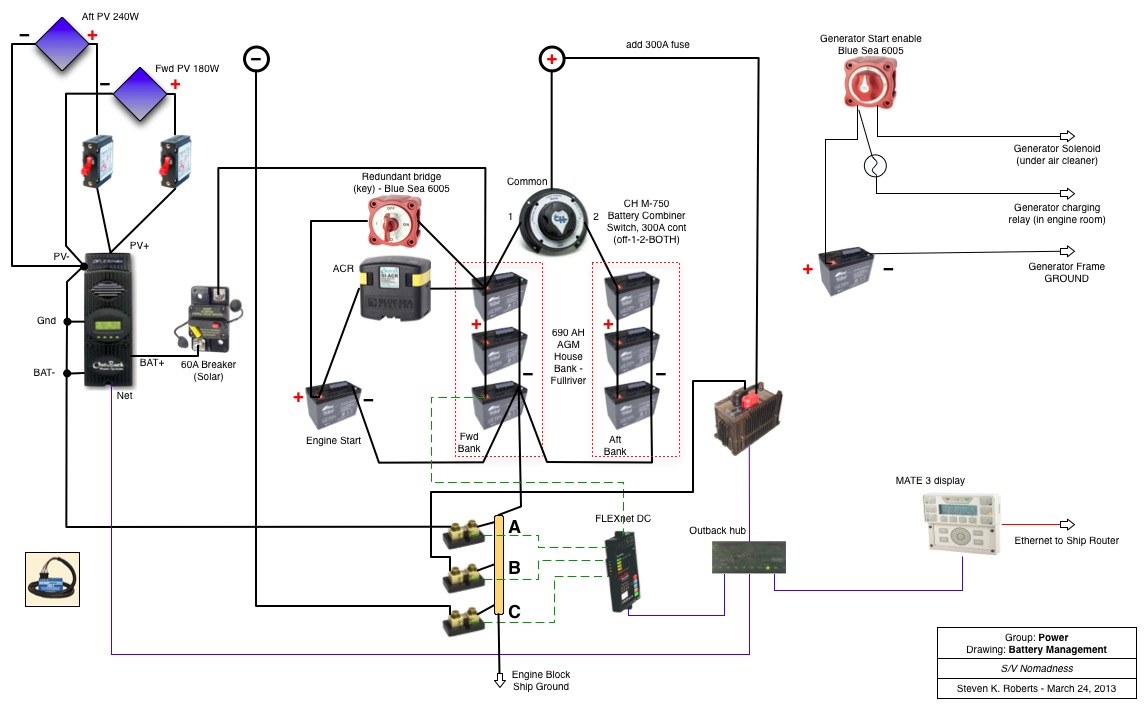
These schematics document the new power distribution system, and include a homebrew replacement for the original Yanmar generator control panel. At the bottom is a drawing of the overall battery management system, including Outback inverter/charger.
For fans of wire dressing (and yes, there’s a niche for all weird people great and small) your panels are extremely pleasing to the eye!
It strikes me that if you moved breaker locations it may well have been necessary to splice conductors. Given the scrupulous style of the work you’re doing here, if you did have to extend cables, what method did you use?
Hi Doug… thanks for the kind words! So far in this region I have managed to avoid in-line splicing… where old wires were too short (or, in some cases, made of a very low strand-count stiff heavy stuff that made me nervous), I simply replaced them. Fortunately, breaker-panel load wiring all goes to the terminal board inside the power bay, so I didn’t have to deal with long-lines disappearing into a wiring harness (on this part of the job, anyway). But when I do, unless particularly paranoid, I use butt crimps with heat-shrink sleeves (Panduit, usually), with a ratchet crimper to do the deed up to #10 or so, and a hydraulic one for the big stuff.
Thank you, Steve. Splices are one of those things that bother me terribly. I suppose that means I’m having a good life. 🙂
I’ve found that butt crimps solder nicely, after being crimped. I’ve done that in a few places where I wasn’t happy about the prospects for keeping moisture permanently at bay.
Sometimes, in such settings, I goop them after being crimped… and then encapsulate with Rescue Tape while still wet. But true… it is good to worry about splices!