Winnebiko II Console Fabrication
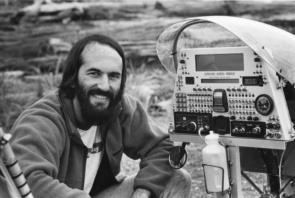
I’ve always been something of a control-panel geek, and once I had committed to building the Winnebiko II and heading out again, the project became focused on console design. If I had learned anything from that first 10,000 miles, it was that the key to this whole adventure would be full access to all on-board tools… while riding. I wanted to be able to write and do email via the binary handlebar keyboard, communicate via voice or packet data on 2-meter ham radio, control the bike’s security system, track performance, and have full access to the bicycle control processor as well as system power management. The summer of 1986 thus became an intense development project, with a mad focus on completing mechanical packaging before zooming across the US to display the bike at Expo 86 (Vancouver BC) in late August… whereupon we holed up on Bainbridge Island for another month while I finished the electronics and wrote the software with an eye on the weather. Good times.
This photo essay shows some of what went into this machine. All the photos can be clicked for larger versions.
Winnebiko II Console Fabrication
by Steven K. Roberts
It began, of course, with a panel design… there was a very tight envelope defined by pedal clearance and visibility, so I found myself working hard to fit it all in. Here, I’m working on the actual-size drawing that would be used to drive the machining… CAD tools were still in the rarefied domain of big engineering companies, so I did it with old-fashioned templates:
Meanwhile, we had to figure out how this would be packaged on the bike… the intent was to have an enclosure inside a fairing, with a solar panel on top, and surfaces that could unfold to give access to the innards without tools. As always in these projects, I had superb help from Really Smart Friends who had much to teach me. Glenn Glassner was one… in this photo, he is staring at the panel mockup and thinking about how we were going to deal with the structural issues…
This turned into a stepped cabinet made of .062 aluminum sheet, with a clamping interface assembly that would affix it to the bike’s head tube at the forward end (with those two columns of 7075 alloy in the photo above supporting the aft end). Here, Glenn is using the bending brake to create the floor of the enclosure:
Once the front panel surface was fabricated from .090 aluminum (with flanges bent back and TIG-welded for stiffness), it was time for the first reality check!
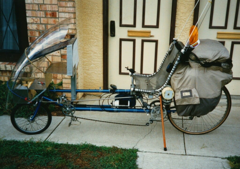
With a panel drawing taped to the substrate, I had lots of fun riding around doing a usability study. Here it is in front of my apartment near Arlington (Columbus, Ohio neighborhood), with the Zzipper fairing bungeed on top.
In this view, you can see the 10-watt Solarex panel that forms the “roof” of the enclosure, as well as the red handles of the toggle clamps above the head tube. (This later proved to be the only real weakness in the design… as unsprung load, it not only started to propagate cracks in the aluminum panel adjacent to the mount, but it tended to brinell the headset bearings.)
With that, it was back to the shop… and some superstar help from John David Call, the steel guitarist with Pure Prairie League (Amie).
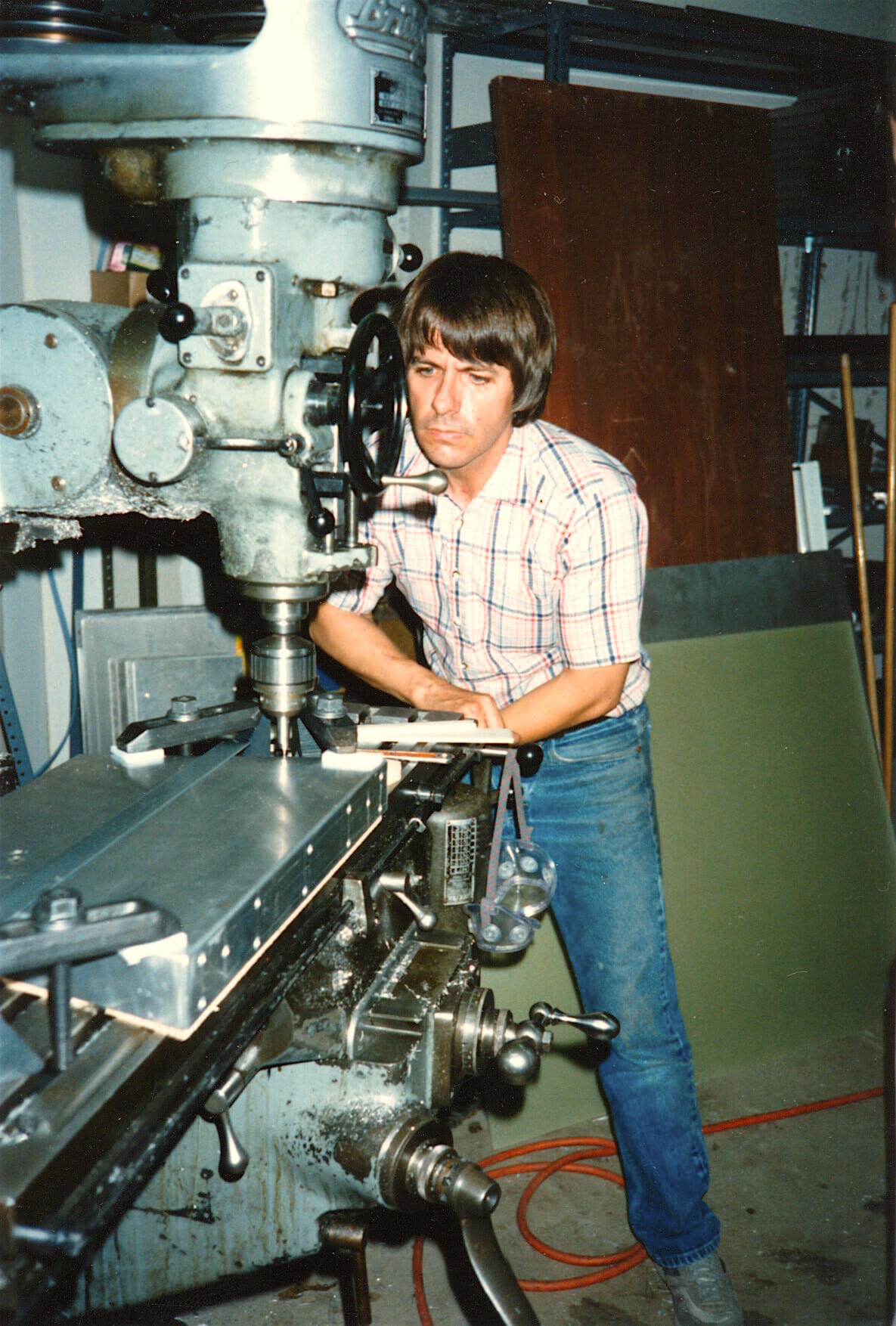
He was developing a lightweight digital soundstage amplifier at his shop in Columbus, and gave me my first lessons in using a Bridgeport milling machine… something that lingered in my mind for years until I finally bought one for my shop in Friday Harbor over a quarter-century later (named Cecil, since Cecil be ‘da Mill).
He and Glenn coached me through the tricky bits, taking the helm when needed.
One of the nice features of this panel was a surface-abrasion resistant polycarbonate window over both of the LCD screens (the hacked Model 100 display at the top, and a little 2-line unit below that for the bicycle control processor). We milled flanges on the Lexan to make the surface flush with the front of the panel. Here was the next reality-check before getting into electronics packaging:
At this point, it was time to clean up the metal with the bead blaster…
This was followed by meticulous application of all the switch legends. I used Letraset transfers, with an intermediate sheet that let me lay down each one and then center it as a group over the appropriate spot on the panel (later photos show the lettering). Work in progress:
Once that was all done, I applied 20 cycles of Krylon spray coating, with a low-temp baking cycle after each group of four. Silly boy, not using a carbon respirator… we were young and immortal then.
Then the fun could begin!
This is Maggie, my girlfriend of the epoch, who would be joining me in this phase of the adventure… 6,000 miles on our bikes, followed by a year-long speaking tour rumbling around the US in a converted school bus.
With front-panel hardware mounted, I could start working on the interface board that connected the 68HC11 to various resources including the hacked Model 100 main board (I had to pretend to be its keyboard with a chunk of code that interpreted the chording bits from my handlebars). I was using one of my favorite prototyping methods… insulation displacement with #30 Kynar wire, much lower-profile than wirewrap.
Things quickly took shape. By September, the major electronic components were all installed (though not yet cabled). In this photo, you can see the pair of Saft NiCad batteries, the Yaesu 290 ham rig flanked by the smaller CB, Lemo connectors for the bike wiring harness, and up on top the 68HC11 piggybacked on its interface board as well as the Model 100 laptop board. Down in the well over the front wheel, there is a Terminal Node Controller (TNC) for packet radio, along with the Votrax speech synthesizer and an UNGO box security system that sensed motion with a 40 kHz field around a blob of mercury (paging me and triggering local speech warnings if disturbed).
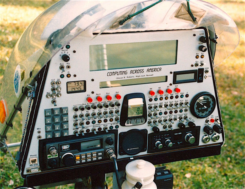
From the front-panel perspective, everything was now at my fingertips. Of course, this was architecturally inflexible, and it didn’t take long before I became frustrated by trying to add new capabilities without being able to easily edit the user interface. But it worked beautifully…
That unit in the middle is the Cat-Eye Solar bicycle computer that was the best speed/cadence/distance/time display at the time. At a Gear Down rally in Florida, I returned to the bike to find a group of cyclists admiring the console. I overheard one guy said, “well, there’s one thing I recognize… a Cat-Eye Solar.”
“Nuh-uh, man. That’s a Cat-Eye Nucular.”
Over on the far right is an altimeter, which was a lifesaver on long mountain climbs (basically telling me to relax and take my time, not look for the summit around every turn). Above that is a small digital voltmeter with a 10-position thumbwheel switch to allow looking at all system voltages, solar charge current, and load. The anachronistic DTMF keypad on the left let me use autopatches on ham-radio repeaters to make phone calls (though in 1988 I added a newfangled cellular phone, replacing the water bottle).
There is an overview page for the whole epoch, along with tech details of the system: The Anatomy of the Winnebiko II.
Just before our departure for Expo ’86 in Vancouver, we threw a little party that was hosted at the Anatec facilities in Dublin, Ohio. This had been my primary consulting client for a while, and we invited some of the key people who had assisted with Winnebiko II fabrication. I contracted a local artist to make little recumbent bicycle wall plaques with engraved thank-you messages, and here is Maggie presenting one to John David Call (the steel guitarist of Pure Prairie League)… his machine shop facilities and extensive help had been instrumental in getting the console built:
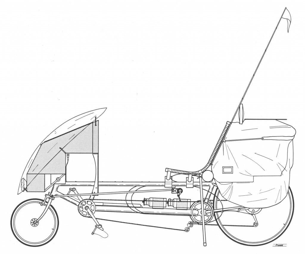
On the road at last! I’ll leave you with this wonderful and technically accurate drawing of the Winnebiko II, done about the same time by my old friend Bob Phare:
Cheers from somewhere… out there….








You must be logged in to post a comment.